


SAM88RI INSTRUCTION SET S3C9228/P9228
6-14
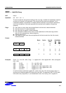
CALL — Call Procedure
CALL dst
Operation: SP ¨ SP – 1
@SP ¨ PCL
SP ¨ SP –1
@SP ¨ PCH
PC ¨ dst
The current contents of the program counter are pushed onto the top of the stack. The program
counter value used is the address of the first instruction following the CALL instruction. The
specified destination address is then loaded into the program counter and points to the first
instruction of a procedure. At the end of the procedure the return instruction (RET) can be used to
return to the original program flow. RET pops the top of the stack back into the program counter.
Flags: No flags are affected.
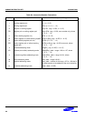
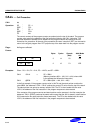
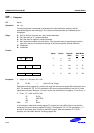
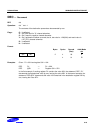
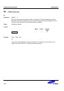
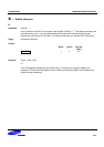
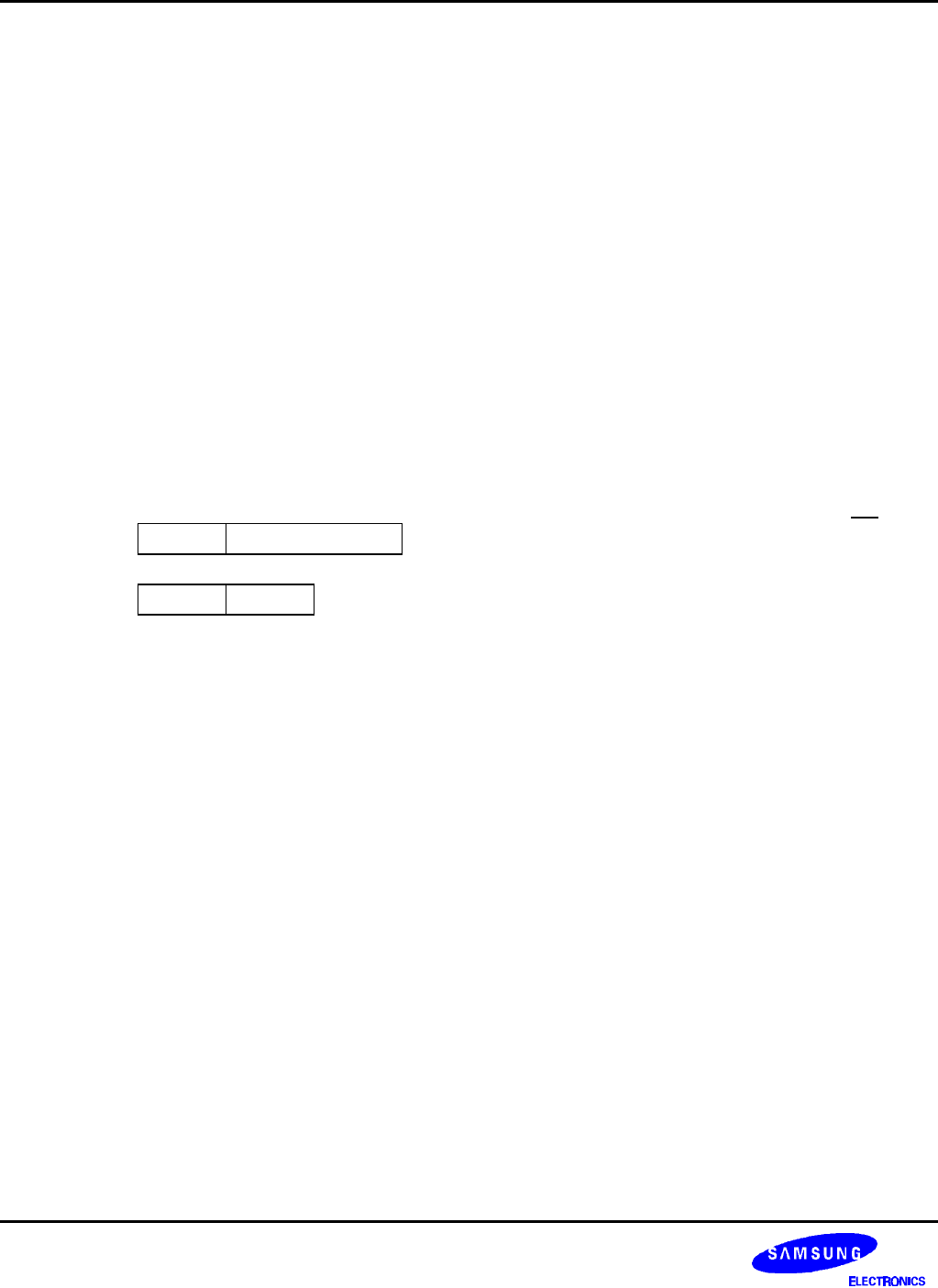
Format:
Bytes Cycles Opcode
(Hex)
Addr Mode
dst
opc dst 3 14 F6 DA
opc dst 2 12 F4 IRR
Examples: Given: R0 = 15H, R1 = 21H, PC = 1A47H, and SP = 0B2H:
CALL 1521H → SP = 0B0H
(Memory locations 00H = 1AH, 01H = 4AH, where 4AH
is the address that follows the instruction.)
CALL @RR0 → SP = 0B0H (00H = 1AH, 01H = 49H)
In the first example, if the program counter value is 1A47H and the stack pointer contains the
value 0B2H, the statement "CALL 1521H" pushes the current PC value onto the top of the stack.
The stack pointer now points to memory location 00H. The PC is then loaded with the value
1521H, the address of the first instruction in the program sequence to be executed.
If the contents of the program counter and stack pointer are the same as in the first example, the
statement "CALL @RR0" produces the same result except that the 49H is stored in stack location
01H (because the two-byte instruction format was used). The PC is then loaded with the value
1521H, the address of the first instruction in the program sequence to be executed.