


S3C9228/P9228 SERIAL I/O INTERFACE
15-1
15 SERIAL I/O INTERFACE
OVERVIEW
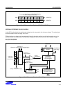
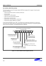
Serial I/O modules, SIO can interface with various types of external device that require serial data transfer. The
components of SIO function block are:
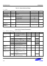
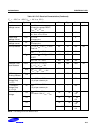
— 8-bit control register (SIOCON)
— Clock selector logic
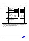
— 8-bit data buffer (SIODATA)
— 8-bit prescaler (SIOPS)
— 3-bit serial clock counter
— Serial data I/O pins (SI, SO)
— Serial clock input/output pin (SCK)
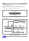
The SIO module can transmit or receive 8-bit serial data at a frequency determined by its corresponding control
register settings. To ensure flexible data transmission rates, you can select an internal or external clock source.
PROGRAMMING PROCEDURE
To program the SIO module, follow these basic steps:
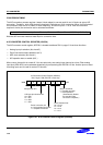
1. Configure the I/O pins at port (SCK/SI/SO) by loading the appropriate value to the P2CON register if
necessary.
2. Load an 8-bit value to the SIOCON control register to properly configure the serial I/O module. In this
operation, SIOCON.2 must be set to "1" to enable the data shifter.
3. For interrupt generation, set the serial I/O interrupt enable bit (SIOCON) to "1".
4. When you transmit data to the serial buffer, write data to SIODATA and set SIOCON.3 to 1, the shift
operation starts.
5. When the shift operation (transmit/receive) is completed, the SIO pending bit (INTPND2.2) are set to "1" and
SIO interrupt request is generated.