


S3C9228/P9228 ADDRESSING MODES
3-7
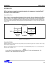
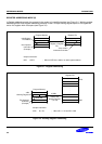
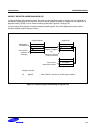
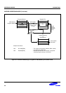
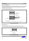
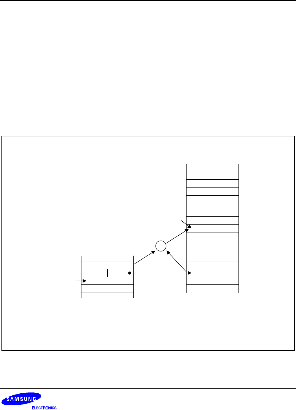
INDEXED ADDRESSING MODE (X)
Indexed (X) addressing mode adds an offset value to a base address during instruction execution in order to
calculate the effective operand address (see Figure 3-7). You can use Indexed addressing mode to access
locations in the internal register file or in external memory.
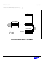
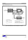
In short offset Indexed addressing mode, the 8-bit displacement is treated as a signed integer in the range of
–128 to +127. This applies to external memory accesses only (see Figure 3-8).
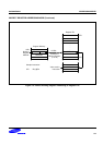
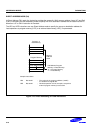
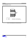
For register file addressing, an 8-bit base address provided by the instruction is added to an 8-bit offset contained
in a working register. For external memory accesses, the base address is stored in the working register pair
designated in the instruction. The 8-bit or 16-bit offset given in the instruction is then added to the base address
(see Figure 3-9).
The only instruction that supports Indexed addressing mode for the internal register file is the Load instruction
(LD). The LDC and LDE instructions support Indexed addressing mode for internal program memory, external
program memory, and for external data memory, when implemented.
dst
OPCODE
Two-Operand
Instruction
Example
Point to One of the
Woking Register
(1 of 16)
Sample Instruction:
LD R0, #BASE[R1] ; Where BASE is an 8-bit immediate value
Program Memory
Register File
4 LSBs
Value used in
Instruction
OPERAND
INDEX
Base Address
~ ~
~ ~
+
src
Figure 3-7. Indexed Addressing to Register File