


TIMER 1 S3C9228/P9228
11-2
Timer 1 Control Register (TACON)
You use the timer 1 control register, TACON, to
— Enable the timer 1 operating (interval timer)
— Select the timer 1 input clock frequency
— Clear the timer 1 counter, TACNT and TBCNT
— Enable the timer 1 interrupt
TACON is located in page 0, at address BBH, and is read/write addressable using register addressing mode.
A reset clears TACON to "00H". This sets timer 1 to disable interval timer mode, selects an input clock frequency
of fxx/512, and disables timer 1 interrupt. You can clear the timer 1 counter at any time during normal operation
by writing a "1" to TACON.3.
To enable the timer 1 interrupt, you must write TACON.7, TACON.2, and TACON.1 to "1".
To generate the exact time interval, you should write TACON.3 and INTPND2.0, which cleared counter and
interrupt pending bit. To detect an interrupt pending condition when T1INT is disabled, the application program
polls pending bit, INTPND.2.0. When a "1" is detected, a timer 1 interrupt is pending. When the T1INT sub-
routine has been serviced, the pending condition must be cleared by software by writing a "0" to the timer 1
interrupt pending bit, INTPND2.0.
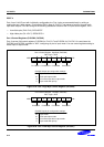
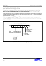
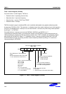
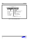
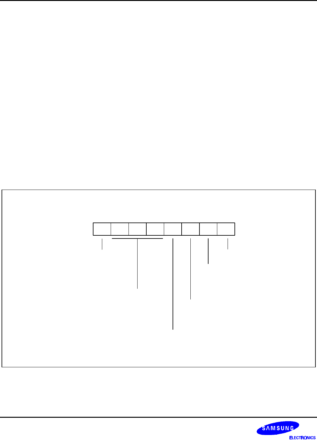
Timer A Control Register (TACON)
BBH, R/W
.7 .6 .5 .4 .3 .2 .1 .0MSB LSB
Timer 1/A interrupt enable bit:
0 = Disable interrupt
1 = Enable interrupt
Not used
Timer 1/A counter enable bit:
0 = Disable counting operation
1 = Enable counting operation
Timer 1/A counter clear bit:
0 = No affect
1 = Clear the timer 1/A counter (when write)
One 16-bit timer or Two 8-bit timers
mode:
0 = Two 8-bit timers mode (Timer A/B)
1 = One 16-bit timer mode (Timer 1)
Timer 1/A clock selection bits:
000 = fxx/512
001 = fxx/256
010 = fxx/64
011 = fxx/8
100 = fxx
101 = fxt (sub clock)
110 = T1CLK (external clock)
111 = Not available
Figure 11-1. Timer 1 Control Register (TACON)