


I/O PORTS S3C9228/P9228
9-6
PORT 1
Port 1 is an 4-bit I/O port with individually configurable pins. Port 1 pins are accessed directly by writing or
reading the port 1 data register, P1 at location E5H in page 0. P1.0-P1.3 can serve as inputs (with or without pull-
up), as outputs (push-pull or open-drain) or you can be configured the following functions.
— Low-nibble pins (P1.0-P1.3): AD0-AD3, INT
Port 1 Control Register (P1CON)
Port 1 has a 8-bit control register: P1CON for P1.0-P1.3. A reset clears the P1CON register to "00H", configuring
pins to input mode. You use control register setting to select input or output mode (push-pull or open-drain) and
enable the alternative functions.
When programming this port, please remember that any alternative peripheral I/O function you configure using
the port 1 control register must also be enabled in the associated peripheral module.
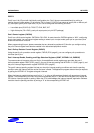
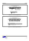
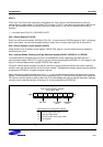
Port 1 Pull-up Resistor Control Register (P1PUR)
Using the port 1 pull-up resistor control register, P1PUR (F0H, page 0), you can configure pull-up resistors to
individual port 1 pins.
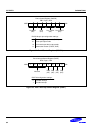
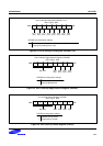
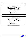
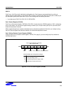
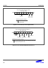
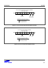
Port 1 Interrupt Enable, Pending, and Edge Selection Registers (P1INT, INTPND1.7-.4, P1EDGE)
To process external interrupts at the port 1 pins, three additional control registers are provided: the port 1
interrupt enable register P1INT (F1H, page 0), the port 1 interrupt pending bits INTPND1.7-.4 (D6H, page 0), and
the port 1 interrupt edge selection register P1EDGE (F2H, page 0).
The port 1 interrupt pending register bits lets you check for interrupt pending conditions and clear the pending
condition when the interrupt service routine has been initiated. The application program detects interrupt requests
by polling the INTPND1.7-.4 register at regular intervals.
When the interrupt enable bit of any port 1 pin is "1", a rising or falling edge at that pin will generate an interrupt
request. The corresponding INTPND1 bit is then automatically set to "1" and the IRQ level goes low to signal the
CPU that an interrupt request is waiting. When the CPU acknowledges the interrupt request, application software
must the clear the pending condition by writing a "0" to the corresponding INTPND1 bit.
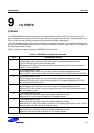
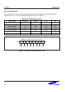
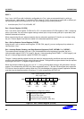
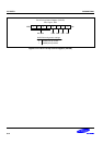
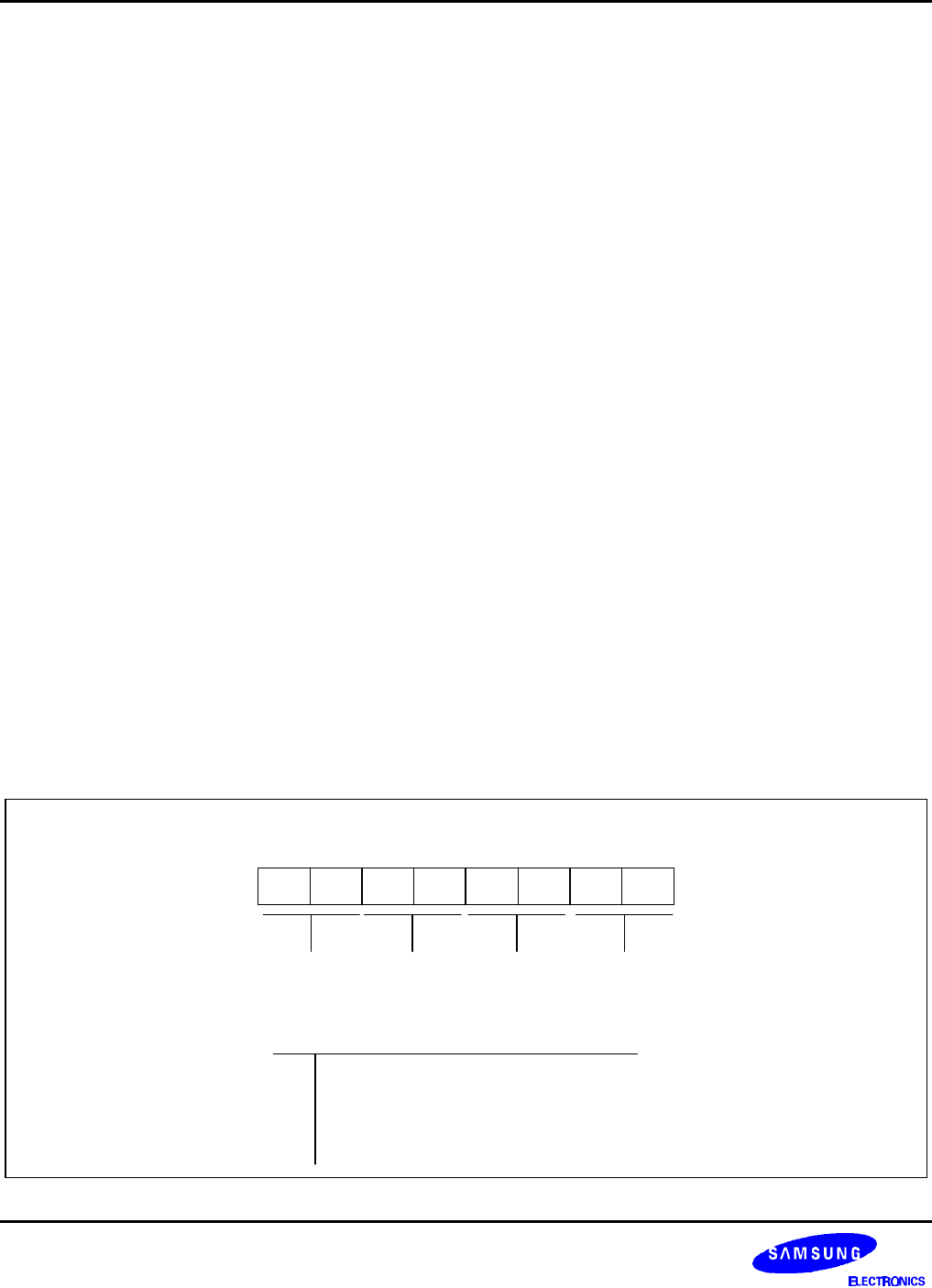
Port 1 Control Register (P1CON)
EFH, Page 0, R/W
.7 .6 .5 .4 .3 .2 .1 .0MSB LSB
P1.3/AD3
(INT)
P1CON bit-pair pin configuration settings:
00
01
10
11
N-channel open-drain output mode
Alternative function (AD0,AD1, AD2, AD3)
P1.2/AD2
(INT)
P1.1/AD1
(INT)
P1.0/AD0
(INT)
Push-pull output mode
Schmitt trigger input mode
Figure 9-7. Port 1 Control Register (P1CON)