


1-2
CAST-AU4/B2521E
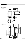
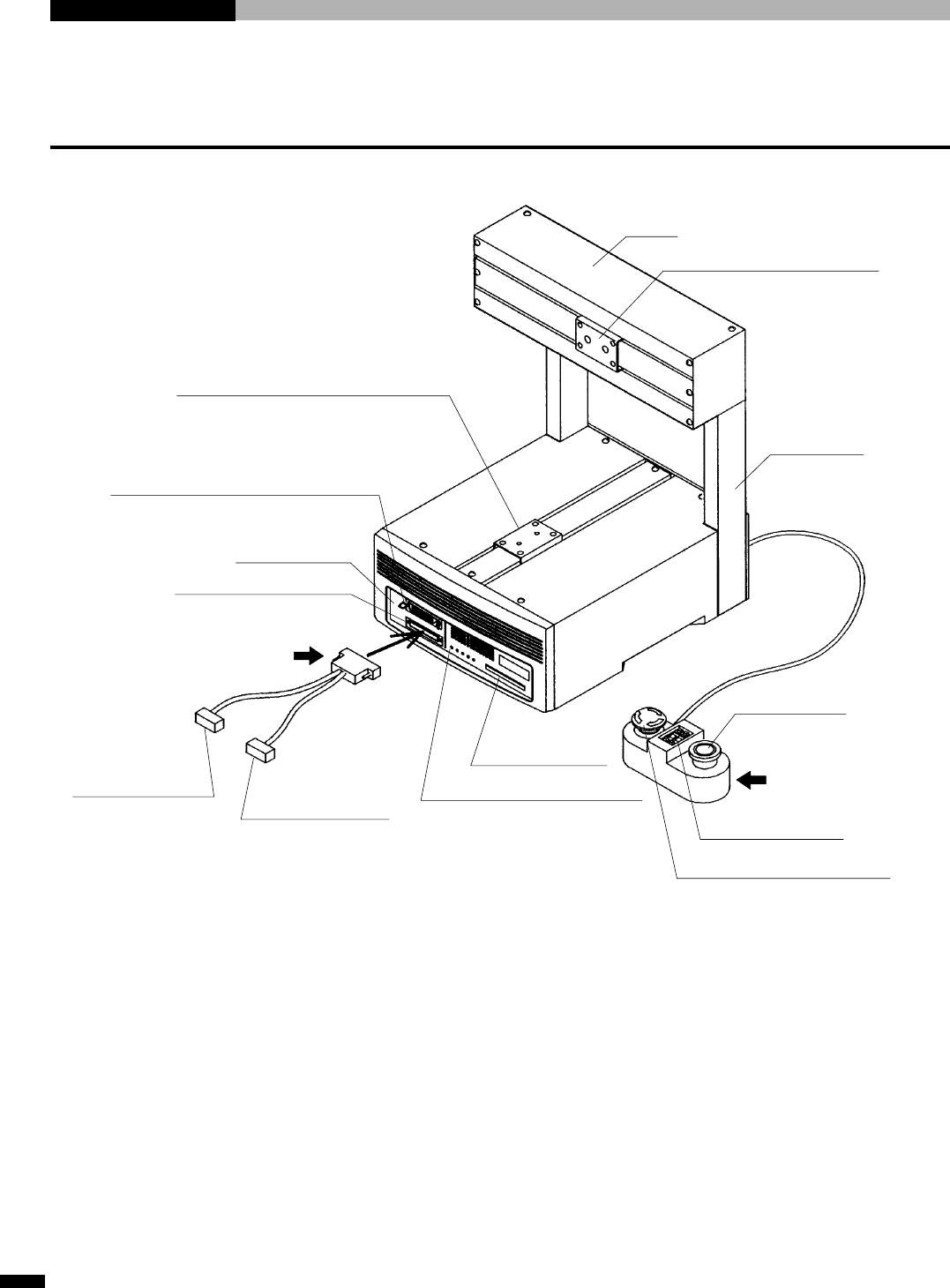
1-1 Nomenclature
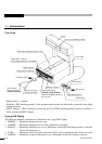
Front View
* Debug station • • • Option
Either the “SRX teaching pendant” or the program transfer cable can be directly connected to the debug
station connector.
* EJECT button • • • When inserting or removing the CAST-PRO teaching pendant, insert it or remove it
while pressing the EJECT button.
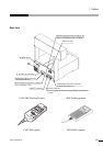
5-gang LED Display
The following machine conditions are indicated on the 5-gang LED display.
1. ERROR ........Illuminates during the error state.
2. ONLINE.......Illuminates during the on-line state. (Illuminates normally.)
3. ROBOT ........Illuminates while the servo is on. (Illuminates continually after home position is checked.
Turned off during stop.)
4. TASK ...........Illuminates while any of the robot task, or PLC task, or peripheral task is being executed.
5. POWER .......Illuminates in green while power is on. Illuminates in red when a battery runs out.
Work table mounting bracket (Y-axis)
X-axis
Unit or tool mounting bracket
X-axis stand
START button
Operation box
PROGRAM switch
STOP button
Memory card slot
5-gang LED display
(POWER, TASK, ROBOT,
ONLINE, ERROR indications
from the left)
RS 232C program
transfer connector
SRX teaching
pendant connector
*To debug station
Debug station connector
*EJECT button
TECH. PEN. connector
(for teaching pendant of CAST-PRO)