


2-8
CAST-AU4/B2521E
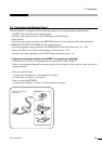
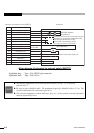
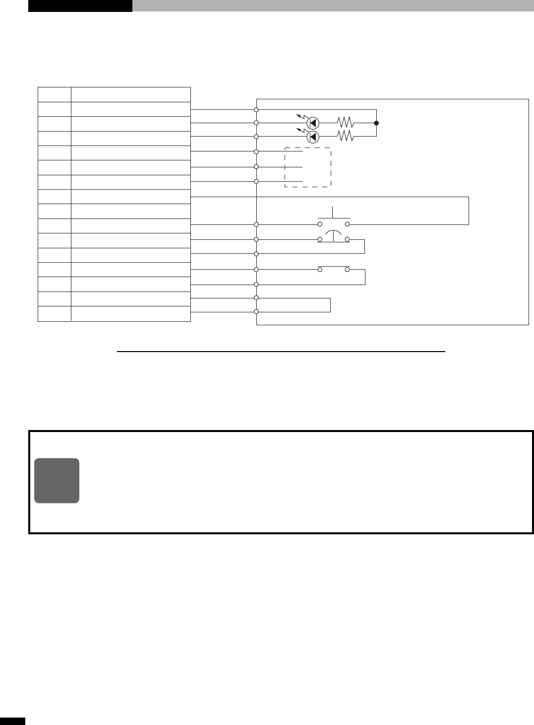
Wiring diagram of connector for external switch (SAFETY)
Applicable plug Type : DA-15PF-N (pin connector)
Applicable shell Type : DA-C4-J10
◆
An external stop button can be inserted between pins-14 and –15, or between
pins-14 and –7.
◆
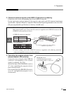
Be sure to use a shielded cable. The maximum length of a shielded cable is 1.5 m. The
external shield must be connected to pin No. 8.
◆
The external equipment (switch, indicator, box, etc.,) to be used for external operation
must be prepared by users.
NOTE
1
2
3
4
5
6
7
8
9
10
11
12
13
14
15
24 V
SA RETURN OUT
SA EMG OUT
Stop RELAY OUT (C)
Stop RELAY OUT (NO)
Stop RELAY OUT (NC)
0V
FG
SA RETURN IN
SA Stop IN (C)
SA Stop IN (NC)
BAR (C)
BAR (NC)
SA Stop ENABLE
0V
Barrier switch, door switch, etc.
Connector for external switch (SAFETY) Safety box
Pin No.
Contents
Max 0.1 A
Connect shield
of the cable
RETURN indicator
Stop indicator
These lines can be freely used by users because
these lines are prepared for independent relay
to be energized at the time of stop.
(Pins-4 and -6 are normally closed.
In a stop, pins-4 and -5 are closed.)
RETURN button
Stop button