


6-3
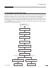
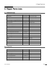
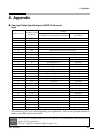
6. Appendix
CAST-AU4/B2521E
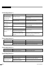
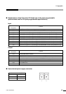
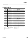
■ Specifications of the Connected I/O (Used only in the semi-programmable
specifications and the full open programmable specifications)
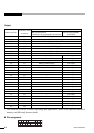
Input
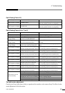
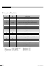
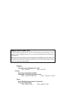
Output
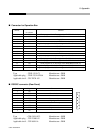
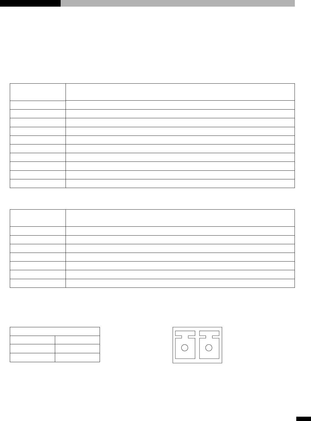
■ User external power supply connector
Contents
START button (White button of operation box)
RETURN button (To be connected from the rear SAFETY connector by user)
Work program No. 1 (First digit of the PROGRAM switch of the operation box (1))
Work program No. 2 (First digit of the PROGRAM switch of the operation box (2))
Work program No. 4 (First digit of the PROGRAM switch of the operation box (4))
Work program No. 8 (First digit of the PROGRAM switch of the operation box (8))
Application program No. 1 (Second digit of the PROGRAM switch of the operation box (1))
Application program No. 2 (Second digit of the PROGRAM switch of the operation box (2))
Application program No. 4 (Second digit of the PROGRAM switch of the operation box (4))
Application program No. 8 (Second digit of the PROGRAM switch of the operation box (8))
I/O names in terms
of software
I23
I24
I25
I26
I27
I28
I29
I30
I31
I32
Contents
START LED (White indicator)
Stop LED (Red indicator)
RETURN indicator (To be connected from the rear SAFETY connector by user)
Stop indicator (To be connected from the rear SAFETY connector by user)
The barrier signal from the rear SAFETY connector becomes valid when the barrier is enabled.
User cannot use it.
User cannot use it.
I/O names in terms
of software
L23
L24
L25
L26
L27
L28
L29
Power connector for I/O
Pin No. Name
1 24 V
2GND
12