


2-10
CAST-AU4/B2521E
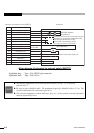
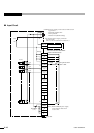
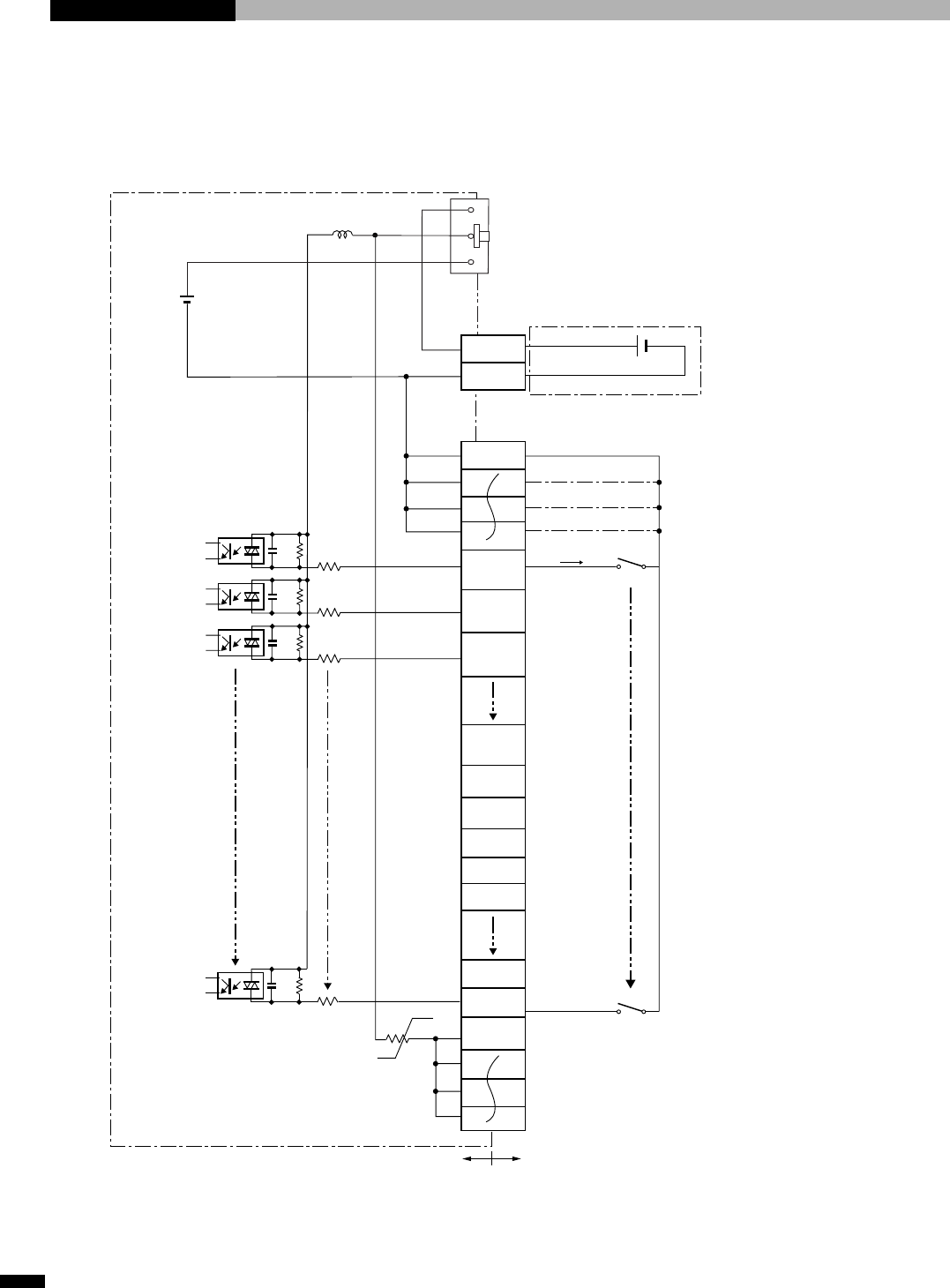
■ Input Circuit
24V
0V
0V IN
24V IN
680pF
470Ω
Maximum 7mA
SI1 operates when
SW1 is ON.
Pin No.
1
35
2
36
3
37
4
51
18
52
19
53
SW1
SW30
Direction of
current
S1
I 1
I 2
I 3
I 4
I 5
I 21
I 22
COM1
0V
SI1
(SYSRUN)
SI3
SI2
SI8
(
Reservation
)
input
(
Reservation
)
input
(
Reservation
)
input
3.3kΩ
TLP280
3.3kΩ
3.3kΩ
User sideController side
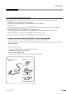
Note1) 24V 0V
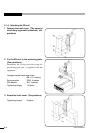
USER I/O power supply source selector slide switch
Up position:
Externally supplied 24V
Down position:
Internal 24V (default setting)
User external power supply connector
PC board side:
MC1.5/2-G-3.81 (Phoenix Contact Inc.)
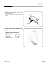
I/O connector
PC board side PCR-E68LMDA
(Honda communication)
Thermistor
(1A)
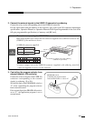
Note1) When USER I/O power supply
source selector slide switch
is set to 24V.