


2-11
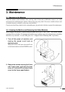
2. Preparation
CAST-AU4/B2521E
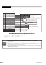
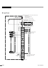
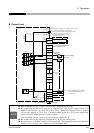
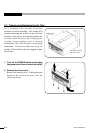
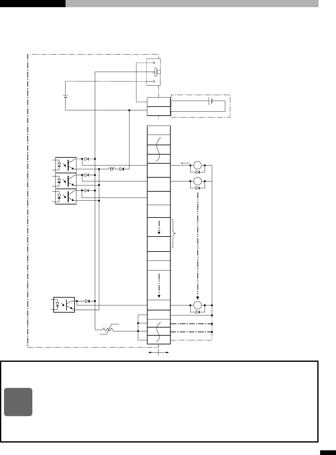
■ Output Circuit
◆
Add the diodes as shown when relay coils are connected as the load.
◆
Be careful that the thermistor operates to shut down the +24 V power supply when 24 V
output is used and the current of 1 A or more flows. Modify the external circuit to reduce
the current capacity to 1 A or less. Thermistor shuts down the +24 V power supply and
returns when the main power is turned on again.
(The maximum current capacity of internal power supply is 1 A.)
◆
Be careful that current capacity is maximum 0.1 A per one output point.
◆
Be sure to use a shielded cable for I/O connection. The maximum length of a shielded
cable is 1.0 m. Use the core conductor of the shielded cable.
NOTE
24V
0V
Note1) 24V 0V
0V IN
24V IN
L 1
L 2
L 22
COM1
0V
SO1
(EMC-OUT)
SO3
(BARRIER)
SO4
(DRIVE)
SO2
(ERROR)
SO8
(
Reservation
)
output
X1
X2
X30
TLP127
20
54
21
68
18
52
19
53
User sideController side
Thermistor (1A)
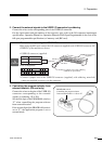
USER I/O power supply source selector slide switch
Up position: Externally supplied 24V
Down position: Internal 24V (default setting)
User external power supply connector
PC board side: MC1.5/2-G-3.81
(Phoenix Contact Inc.)
I/O connector
PC board side PCR-E68LMDA
(Honda communication)
Relay coil voltage
(DC 24V)
Reservation
output
Maximum
0.1A
Direction of
current
Diode
Note1) When USER I/O power supply
source selector slide switch
is set to 24V.
S1