


2-7
2. Preparation
CAST-AU4/B2521E
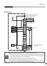
2-2 Connecting the External Signal
The base machine is equipped with the following connectors for external signal communication.
• SAFETY (for external switch) connector (rear)
• External Stop (same function as the STOP button of the main unit)
• Door, barrier
• External return (same operation as the RETURN button in the two operators line mode operation)
• USER INPUT/OUTPUT (EXTERNAL I/O) connector (rear)
• Selecting programs (same operation as the PROGRAM switch of the main unit) : (I3 ~ I10)
• Error reset (There is no switch corresponding to this function.) : (I11)
• External start (same operation as the START button of the main unit) : (I1)
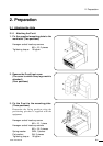
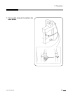
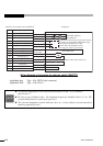
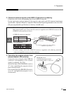
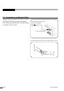
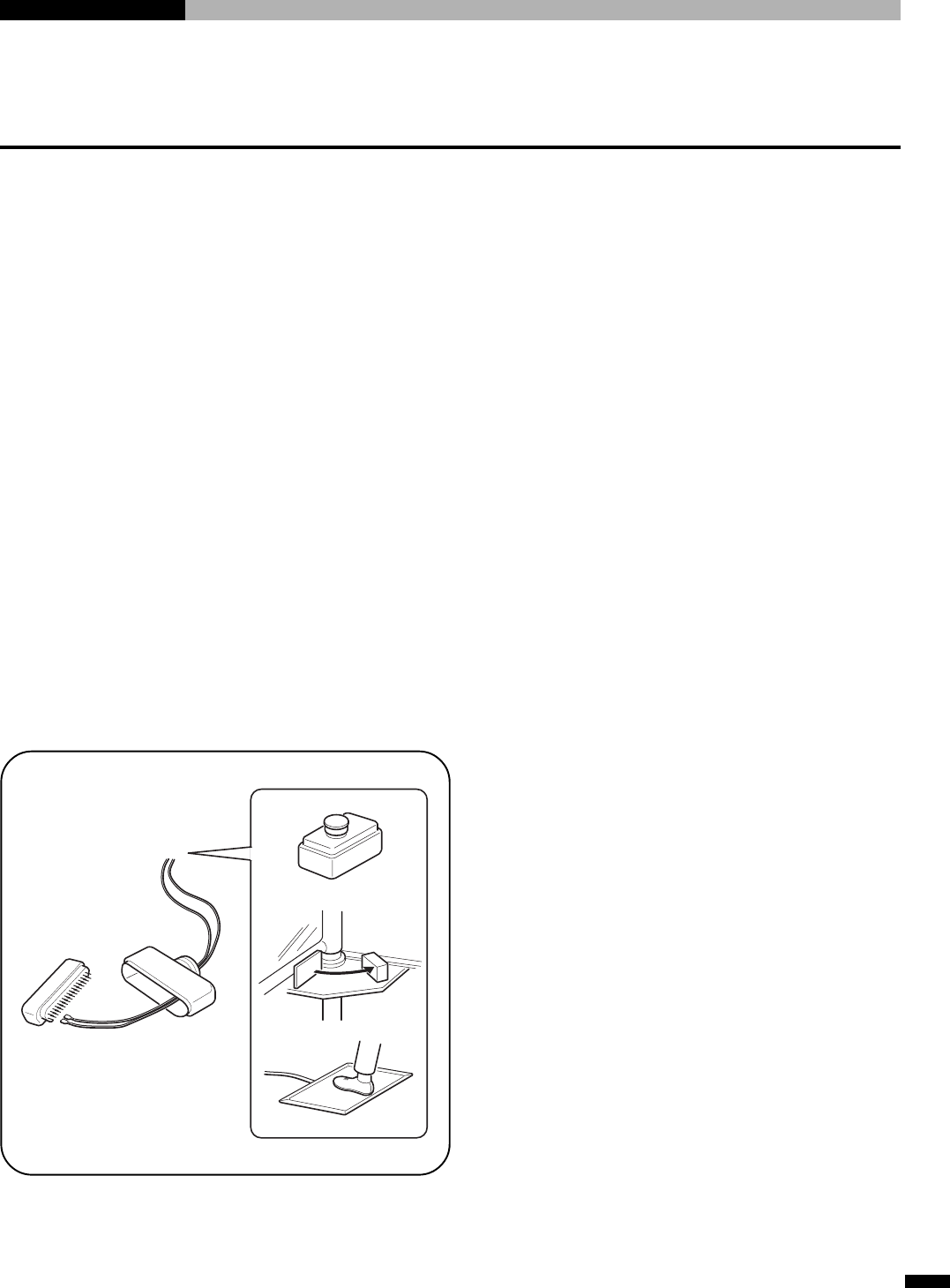
1. Connect an external switch to the SAFETY connector by soldering.
Connect the wires to the corresponding pins of the external switch connector.
Refer to the connector diagram for external switch, for the signals at the respective pins and type of
mating connector.
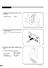
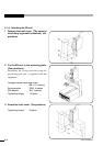
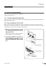
How to control the stop:
• Connect pin-10 and pin-11 to the respective switches.
• Connect pin-14 to pin-15. (or to pin-7)
How to control the RETURN :
• Connect pin-9 and pin-7 (or pin-15) to the respective switches.
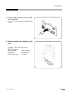
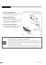
Example of external
stop switch
Switch box
Door switch
Floor mat switch