


6-2
CAST-AU4/B2521E
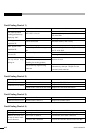
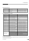
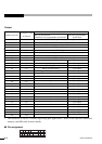
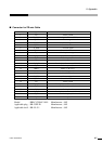
Output
Connector pin No.
20
54
21
55
22
56
23
57
24
58
25
59
26
60
27
61
28
62
29
63
30
64
31
65
32
66
33
67
34
68
I/O names in terms
of software
SO1
SO2
SO3
SO4
SO5
SO6
SO7
SO8
L1
L2
L3
L4
L5
L6
L7
L8
L9
L10
L11
L12
L13
L14
L15
L16
L17
L18
L19
L20
L21
L22
Contents
RK card specification
(including semi-programmable specification)
EMG-OUT, stop switch, stop status output
ERROR, robot error signal
Reserved by system (User cannot use it.)
Drive servo ON signal
ONLINE signal
Reserved by system (User cannot use it.)
Reserved by system (User cannot use it.)
Reserved by system (User cannot use it.)
End of cycle output
Standby output
Error output
During operation output
Unloading position output (during line mode)
*
*
*
*
*
*
*
*
*
*
*
*
*
*
*
*
*
Full-open programmable
specification
User output
User output
User output
User output
User output
User output
User output
User output
User output
User output
User output
User output
User output
User output
User output
User output
User output
User output
User output
User output
User output
User output
* The allocation at L6 to L22 differs depending upon applications. Refer to the Operation Manual of
memory card (RK card) for more details.
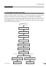
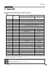
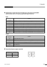
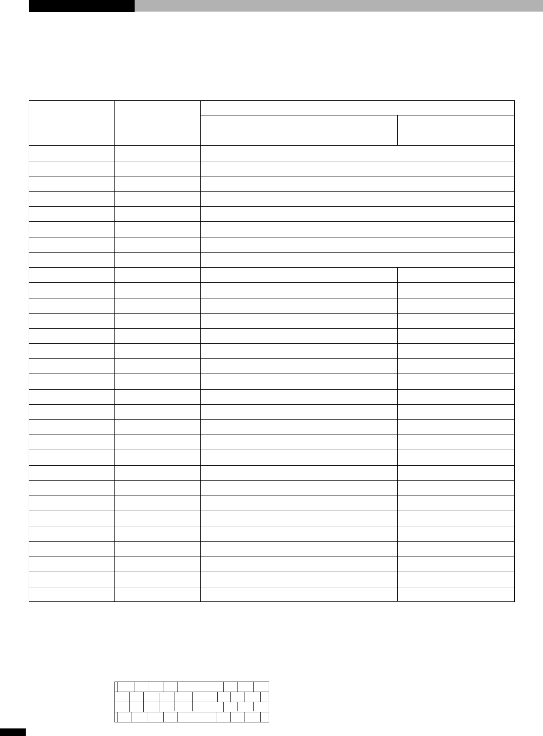
■ Pin assignment
2468
~
30 32 34
13579
~
29 31 33
36 38 40 42
~
64
66 68
35 37 39
41
~
63
65
67