2-13
Setup and Installation: Mechanical
Cable Pin-Outs
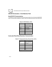
Table 2-1 through Table 2-7 describe the CABLE termination required for attaching an
external cable to the MK1000.
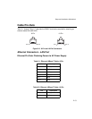
Figure 2-5. 8-Pin and 10-Pin Connectors
Ethernet Connectors - LAN Port
Ethernet Pin-Outs: Obtaining Power via AC Power Supply
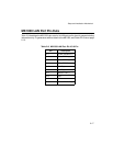
Table 2-1. Ethernet 10Base-T Cable: 8-Pin
Pin Description
Pin 1 TXD (+)
Pin 2 TXD (-)
Pin 3 RXD (+)
Pin 6 RXD (-)
Pin 7 GND
Pin 8 GND
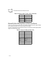
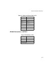
Table 2-2. Ethernet 10Base-T Cable: 10-Pin
Pin Description
Pin 2 TXD (+)
Pin 3 TXD (-)
Pin 1 Pin 8
Pin 1
Pin 10
8-Pin
10-Pin


