Paint Circuit
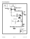
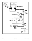
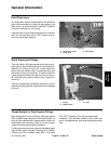
The Line Painter 1200 paint circuit uses a positive dis-
placement diaphragm pump to move paint from the
paint tank to the spray nozzle. The spray pump is a self–
priming diaphragm pump that has a dry crankcase.
The engine drives the spray pump indirectly through pul-
leys and a V–belt. The spray pump belt is always ten-
sioned by a backside idler pulley so the pump is being
rotated whenever the engine is running.
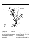
When the pump is rotated, the downward stroke of the
pump’s diaphragm creates suction to allow fluid (paint)
to be drawn from the paint tank to the pump via hoses,
a ball valve (in the paint position) and a 40 mesh screen
filter. Pump design prevents fluid from being pumped
back into the suction line.
Once to the pump, the fluid (paint) is pushed by the up-
ward stroke of the pump’s diaphragm to the pressure
side of the spray system through hoses, control valves
and the spray nozzle. Pump design prevents fluid from
being drawn back into the pump. Maximum pressure in
the system is limited by an adjustable relief valve located
in the pump.
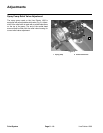
An adjustable pressure regulator is used by the operator
to set paint circuit pressure on the Line Painter 1200.
Flow in excess of the regulator setting is directed back
to the paint tank via a ball valve (in the paint position).
This return flow is used for paint tank agitation. An op
-
tional pressure gauge (if equipped) indicates system
pressure.
A mechanically actuated spool valve is used to turn the
spray nozzle on/off. Spool valve shift occurs when the
operator depresses or releases the paint control lever.
Line Painter 1200 Page 5 – 5 Paint System
Paint
System


