


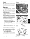

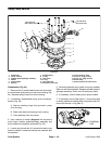
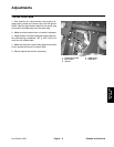
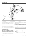
Disassembly (Fig. 36)
1. Operate line painter in the flush mode to clean paint
tubes.
2. Park machine on a level surface, stop engine, en-
gage parking brake and remove key from the ignition
switch. Remove high tension lead from the spark plug
and position the lead away from the spark plug.
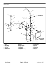
3. Remove spray head components as needed using
Figures 36 and 37 as guides.
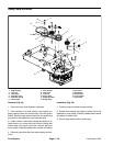
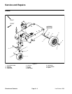
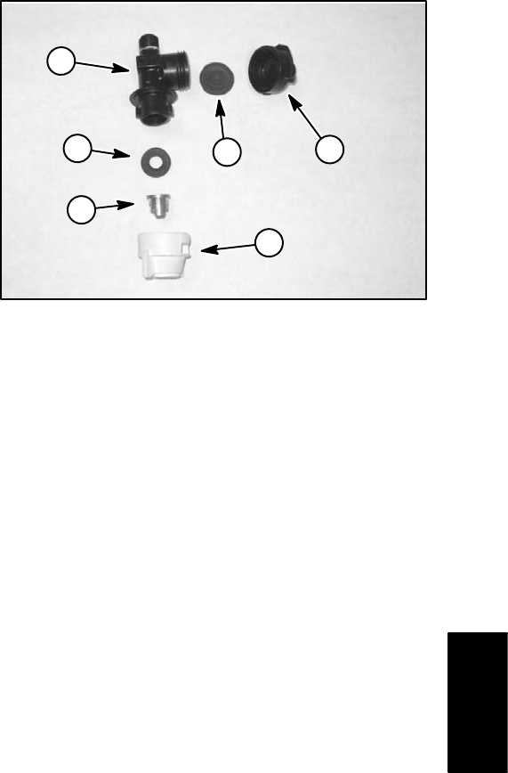
Assembly (Fig. 36)
4
1
3
5
2
6
1. Assemble spray head using Figures 36 and 37 as
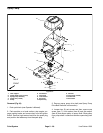
Figure 37
guides. If barb fitting (item 3) or diaphragm nozzle (item
1. Body 4. Adapter cap
10) were removed from nozzle tube, apply Saf–T–Lok
2. Seat gasket 5. Check valve end cap
3. Spray nozzle 6. Check valve diaphragm
PTFE Pipe Sealant (or equivalent) to threads of compo-
nents before assembly (see Thread Sealant for Paint
System Fittings in the General Information section).
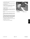
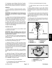
2. Adjust spray head components (see Operator’s
Manual).
Line Painter 1200 Page 5 – 33 (Rev. A) Paint System
Paint
System