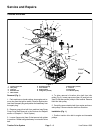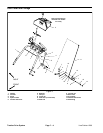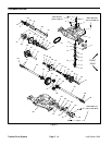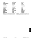
Disassembly (Fig. 3)
1. Park machine on a level surface, stop engine, apply
parking brake and remove key from the ignition switch.
Remove high tension lead from the spark plug and posi
-
tion the lead away from the spark plug.
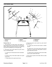
2. Disassemble shift linkage components as needed
using Figure 3 as a guide.
Assembly (Fig. 3)
1. Assemble shift linkage components using Figure 3
as a guide.
2. After assembly of shift linkage components, make
sure that console shift lever movement allows correct
transaxle shifting. If necessary, adjust rod fitting (item
15) location on control rod for proper shifting.
3. Secure high tension lead to spark plug.
Line Painter 1200 Page 7 – 5 Traction Drive System
System
Traction Drive


