


Line Painter 1200 Chassis and ControlsPage 6 – 11
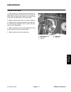
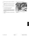
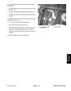
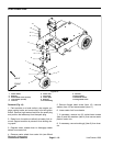
3. Connect castor release cable to castor release det-
ent under front of machine (Figs. 9 and 10):
A. Secure cable clevis to castor release detent with
clevis pin and hair pin.
B. Position cable to chassis bracket.
C. Tighten cable jam nuts to allow castor detent to
completely disengage from front castor when castor
release lever on handle is pulled against handle.
D. Make sure that cable boot is positioned over end
of cable.
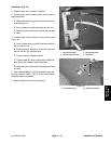
4. Secure high tension lead to spark plug.
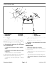
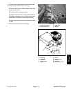
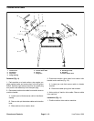
1. Castor release cable
2. Castor release lever
3. Cable clevis
4. Jam nut
Figure 9
1
2
3
4
4
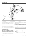
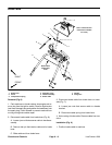
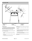
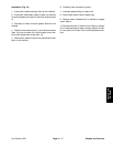
1. Cap screw
2. Flange nut
3. Flat washer
4. Torsion spring
5. Spacer
6. Detent
7. Flange bushing
8. Hair pin
9. Clevis pin
10. Castor release cable
Figure 10
2
3
4
1
5
6
7
8
10
9
Chassis and
Controls