


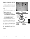
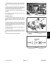

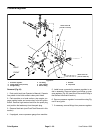

Paint Shutoff Valve Removal (Fig. 18)
1. Drain paint tank (see Operator’s Manual). Operate
line painter in the flush mode to clean paint tubes.
2. Park machine on a level surface, stop engine, en-
gage parking brake and remove key from the ignition
switch. Remove high tension lead from the spark plug
and position the lead away from the spark plug.
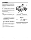
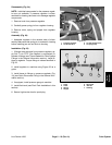
3. Remove flush tank (see Flush Tank Removal in this
section).
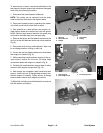
4. Remove inlet and outlet hoses from paint shutoff
valve (Fig. 19) (see Quick Disconnect Fitting in the Gen
-
eral Information section).
5. Disconnect extension spring (item 9) from lever (item
10).
6. Remove hair pin (item 11) and pin (item 12) that se-
cure cable to lever.
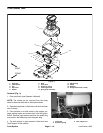
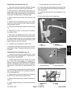
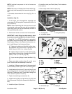
7. Remove two (2) cotterless pins (item 13) that retain
lever to shutoff valve (Fig. 20). Remove lever from valve.
8. Remove flange nut (item 5), cap screw (item 14) and
flat washer (item 15) that secure shutoff valve to tank
support. Remove valve from machine.
9. If needed, remove fittings from shutoff valve.
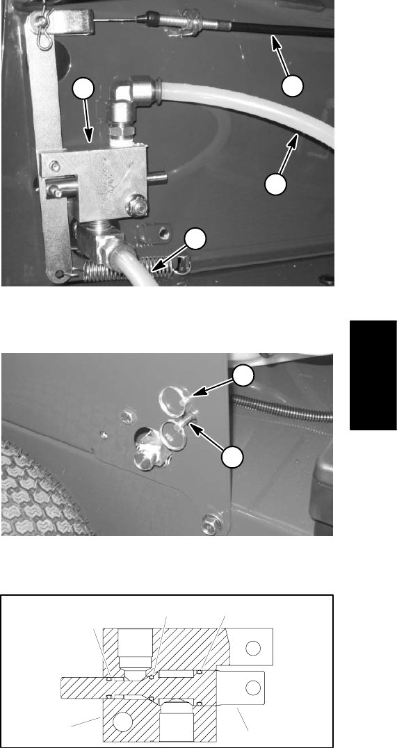
10.If required, push spool from manifold block. Remove
and discard o–rings. Thoroughly clean spool and man
-
ifold block.
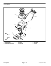
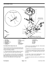
Paint Shutoff Valve Installation (Fig. 18)
1. If spool was removed from manifold block, install
new o–rings on spool. Lightly grease o–rings and spool.
Push spool into manifold block.
2. If fittings were removed from shutoff valve, apply
Saf–T–Lok PTFE Pipe Sealant (or equivalent) to
threads of fittings (see Thread Sealant for Paint System
Fittings in the General Information section). Install fit
-
tings to valve. Torque fittings to values identified in Fig.
18.
3. Position valve to tank support and install cap screw
(item 14), flat washer (item 15) and flange nut (item 5).
Do not fully tighten nut.
4. Position lever to valve and install two (2) cotterless
pins (item 13) to secure lever to shutoff valve.
5. Secure cable to lever with pin (item 12) and hair pin
(item 11).
7. Connect extension spring (item 9) to lever.
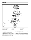
8. Connect inlet and outlet hoses to paint shutoff valve
(Fig. 19) (see Quick Disconnect Fitting in the General In
-
formation section).
9. Install flush tank (see Flush Tank Installation in this
section).
10.Secure high tension lead to spark plug.
1
4
2
3
Figure 19
1. Cable 3. Inlet hose
2. Outlet hose 4. Paint shutoff valve
1
2
Figure 20
1. Pivot cotterless pin 2. Spool cotterless pin
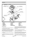
1
2
34
5
Paint
System
Figure 21
6. Tighten flange nut (item 5) to secure shutoff valve to
1. Manifold block 4. O–ring
machine.
2. Spool 5. O–ring
3. O–ring
Line Painter 1200 Page 5 – 21 (Rev. A) Paint System