


Line Painter 1200Page 5 – 12Paint System
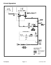
Service and Repairs
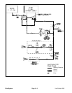
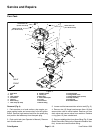
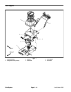
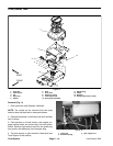
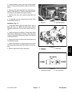
Paint Tank
1. Paint tank
2. Nut
3. Tank support
4. Flat washer
5. Jam nut
6. Elbow fitting
7. Tank clamp (2 used)
8. Rubber washer
9. Outlet port
10. Ball valve
11. Recirculation port
12. O–ring
13. Drain valve
14. Elbow fitting
15. Valve bracket
16. Flange head screw
17. Flange head screw (4 used)
18. Pump assembly
19. Flush tank
20. Slotted washer
Figure 4
FRONT
RIGHT
2
3
4
1
5
6
7
8
10
11
12
9
13
15
14
20
5
8
10
16
17
18
19
144 to 156 in–lb
(16.3 to 17.6 N–m)
192 to 216 in–lb
(21.7 to 24.4 N–m)
192 to 216 in–lb
(21.7 to 24.4 N–m)
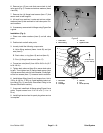
Removal (Fig. 4)
1. Park machine on a level surface, stop engine, en-
gage parking brake and remove key from the ignition
switch. Remove high tension lead from the spark plug
and position the lead away from the spark plug.
2. Drain paint tank (see Operator’s Manual). Remove
tank lid and strainer.
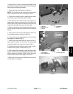
3. Loosen nut that secures drain valve to tank (Fig. 5).
4. Remove two (2) flange head screws (item 16) that
secure drain valve to valve bracket. Remove nut from
drain valve and remove valve from machine. Retrieve
o–ring (item 12) from outside tank.
5. Remove agitation tube from elbow fitting (Fig. 5) (see
Quick Disconnect Fitting in the General Information sec-
tion). Loosen and remove elbow fitting.