Line Painter 1200Page 5 – 20Paint System
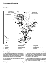
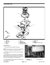
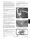
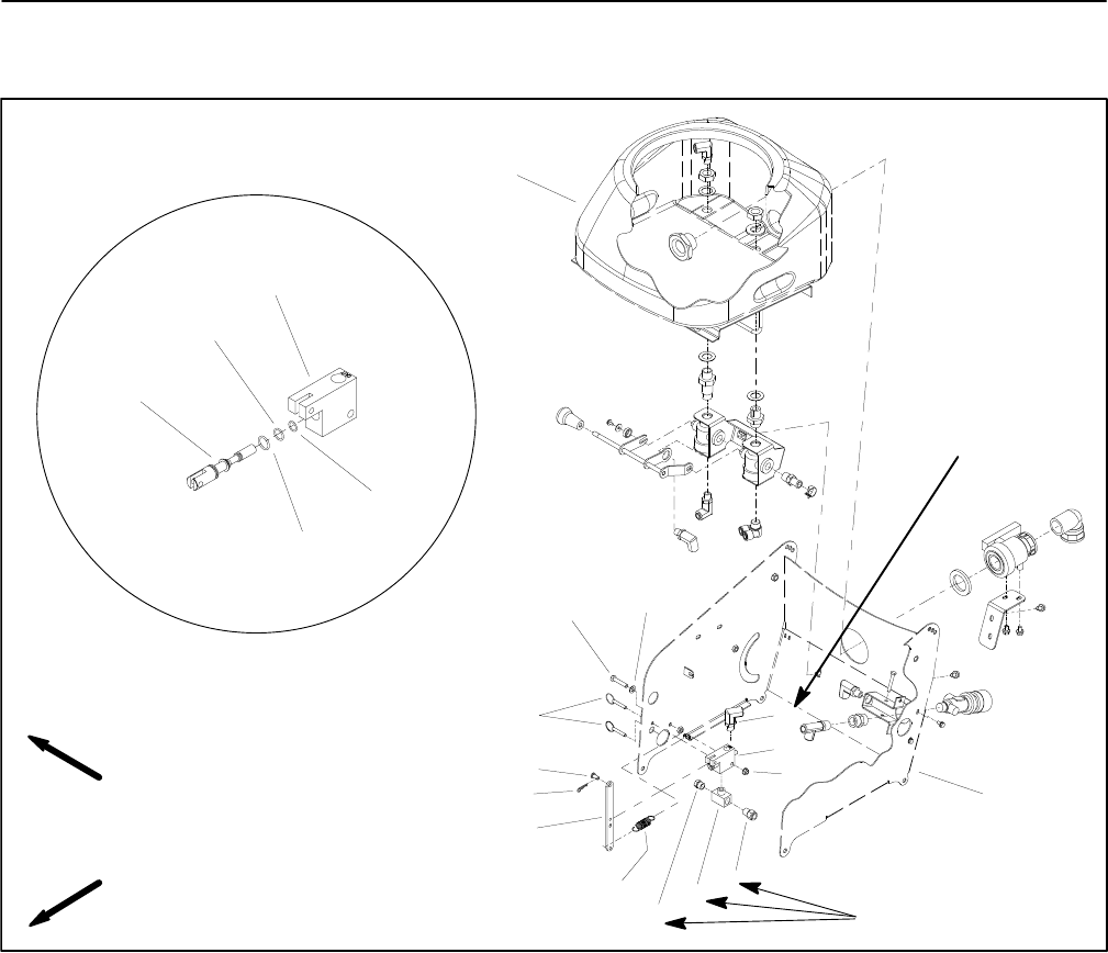
Paint Shutoff Valve
1. Paint tank
2. Tank support
3. Elbow fitting
4. Paint shutoff valve
5. Flange nut
6. Straight fitting
7. Tee fitting
8. Plug
9. Extension spring
10. Lever
11. Hair pin
12. Pin
13. Cotterless pin
14. Cap screw
15. Flat washer
16. Manifold block
17. O–ring
18. O–ring
19. O–ring
20. Spool
Figure 18
FRONT
RIGHT
2
3
4
1
5
6
7
8
10
11
12
9
13
15
14
192 to 216 in–lb
(21.7 to 24.4 N–m)
144 to 156 in–lb
(16.3 to 17.6 N–m)
20
18
19
16
17
PAINT SHUTOFF VALVE
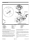
Paint Shutoff Valve Spool (Fig. 18)
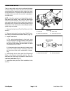
The spool can be removed from the paint shutoff valve
without removing the complete valve from the machine
using the following procedure:
1. Drain paint tank (see Operator’s Manual). Operate
line painter in the flush mode to clean paint tubes.
2. Park machine on a level surface, stop engine, en-
gage parking brake and remove key from the ignition
switch. Remove high tension lead from the spark plug
and position the lead away from the spark plug.
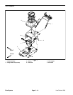
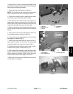
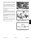
3. Remove two (2) cotterless pins (item 13) that retain
lever to shutoff valve (Fig. 20).
4. Slide lever out of manifold block and place to side.
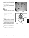
5. Pull spool from manifold block. Remove and discard
o–rings from spool. Thoroughly clean spool and man-
ifold block.
6. Install new o–rings on spool. Lightly grease o–rings
and spool. Push spool into manifold block.
7. Install lever and secure with two (2) cotterless pins
(item 13).


