


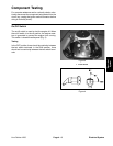
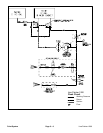

Flush Circuit
The Line Painter 1200 paint circuit uses a positive dis-
placement diaphragm pump to move fluid (water) from
the flush (water) tank through the spray system. The
spray pump is a self–priming diaphragm pump that has
a dry crankcase.
When the pump is rotated, the downward stroke of the
pump’s diaphragm creates suction to allow fluid (water)
to be drawn from the flush tank to the pump via hoses,
a one–way check valve, a ball valve (in the flush posi
-
tion) and a 40 mesh screen filter.
Once to the pump, the fluid (water) is pushed by the up-
ward stroke of the pump’s diaphragm to the pressure
side of the spray system through hoses, control valves
and the spray nozzle. Maximum pressure in the system
is limited by an adjustable relief valve located in the dia
-
phragm pump.
Flow in excess of the adjustable pressure regulator set-
ting is directed back to the flush (water) suction line via
a ball valve (in the flush position).
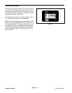
Flow through the flush circuit is used to dilute and re-
move paint from the ball valves, screen filter, spray
pump, regulator, spool valve, spray nozzle and all
hoses.
A one–way check valve is positioned between the flush
(water) tank and the ball valve (see schematic). This
check valve prevents paint from entering the flush (wa
-
ter) tank when the paint/flush lever is moved from the
paint position to the flush position and while the machine
is operated in the flush mode.
NOTE: If the flush system is not cleaned after use, di-
luted paint may cause check valve and associated
hoses to become blocked. If the check valve is stuck
open, paint may enter the flush (water) tank when the
paint/flush lever is moved from the paint position to the
flush position. If the check valve is stuck closed, the flush
system may not operate.
Line Painter 1200 Page 5 – 7 Paint System
Paint
System