


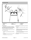

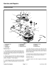
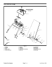
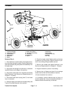
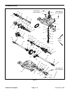

2. Position traction drive belt to idler pulley and bracket
making sure that belt is placed between pulley and guide
on bracket (Fig. 2). Tighten cap screw (item 12) and lock
nut (item 3) to secure idler pulley to idler bracket.
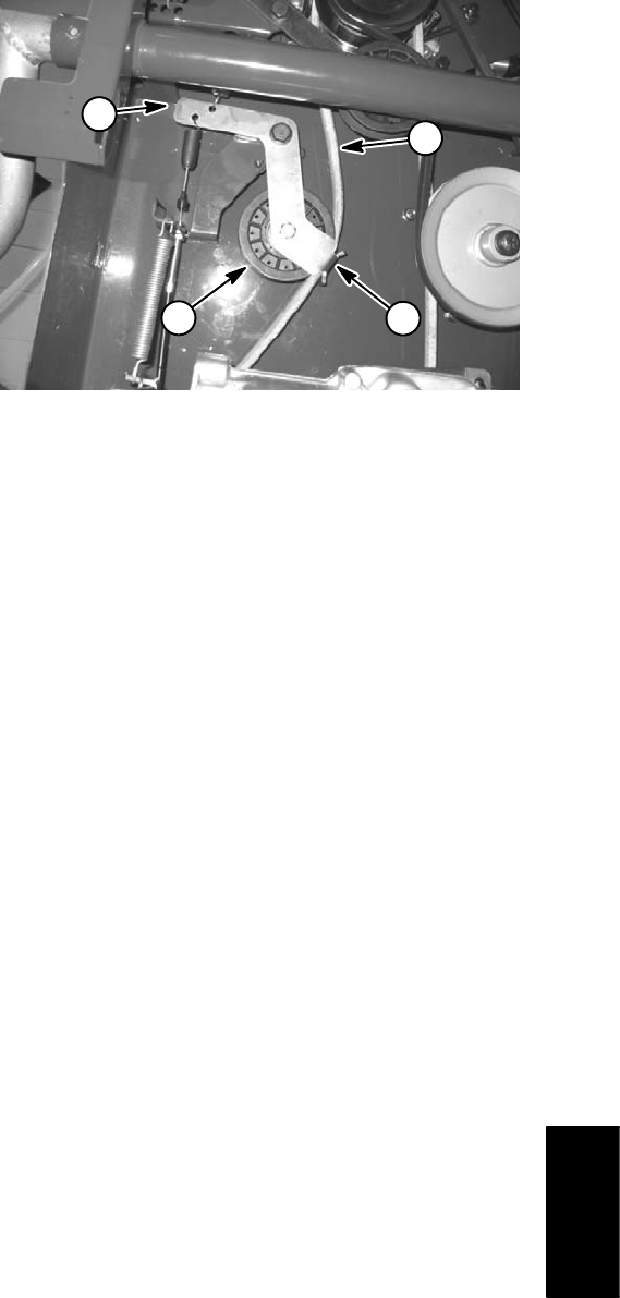
3. Tension the traction drive belt by depressing the trac-
tion drive lever operator control. Rotate belt guides to al-
low from .060” to .130” (1.5 to 3.3 mm) clearance
between guide and tensioned traction drive belt. Tighten
lock nuts to secure guides in place.
4. Install pump drive belt to machine (see Spray Pump
Drive Belt Installation in the Service and Repairs section
of Chapter 5 – Paint System).
5. Check traction drive belt cable adjustment (see Trac-
tion Drive Cable in the Adjustments section of Chapter
Figure 2
1
4
3
2
1. Traction drive belt 3. Idler pulley
6 – Chassis).
2. Idler bracket 4. Bracket belt guide
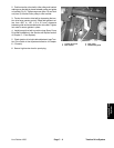
6. Secure high tension lead to spark plug.
Line Painter 1200 Page 7 – 3 Traction Drive System
System
Traction Drive