Line Painter 1200 Page 5 – 13 Paint System
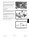
6. Remove two (2) jam nuts that secure tank to ball
valve ports (Fig. 5). Locate and retrieve washers (items
4 and 20).
7. Remove four (4) flange head screws (item 17) that
secure tank to tank support.
8. Lift tank from machine. Locate and retrieve rubber
washers (item 8) that seal tank to ball valve ports. Dis-
card washers.
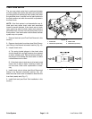
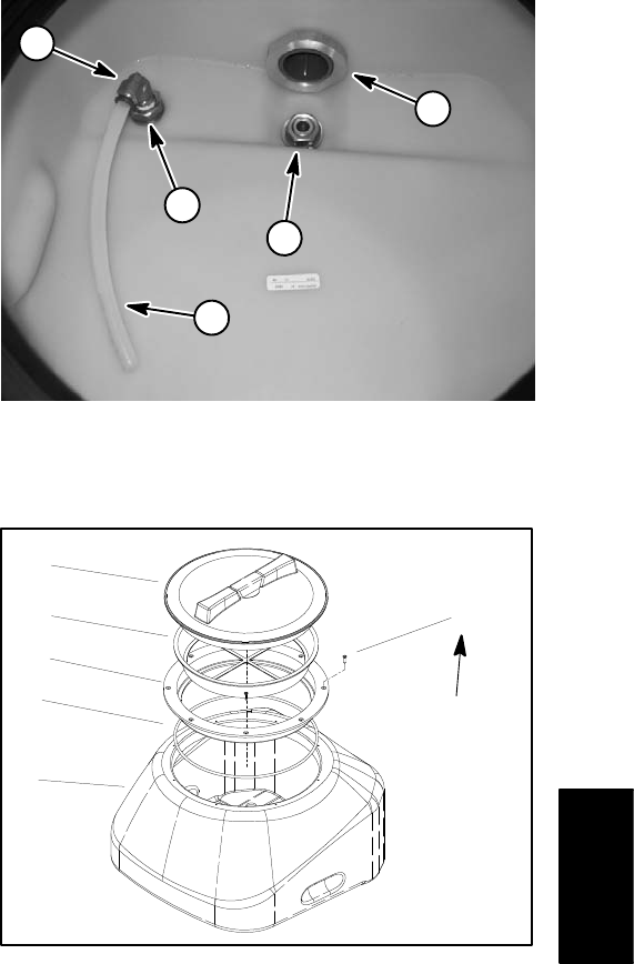
9. If necessary, remove tank lid flange using Figure 6 as
a guide.
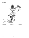
Installation (Fig. 4)
1. Place new rubber washers (item 8) on ball valve
ports.
2. Position tank on ball valve ports.
3. Loosely install the following components:
A. Valve fitting washers (items 4 and 20) and jam
nuts (item 5).
B. Drain valve, o–ring (item 12) and nut (item 2).
C. Four (4) flange head screws (item 17).
4. Torque jam nuts (item 5) from 192 to 216 in–lb (21.7
to 24.4 N–m).
5. Tighten drain valve nut (item 2) to secure drain valve
to tank. Then tighten two (2) flange head screws (item
16) that secure drain valve to valve bracket. Finally tight-
en the four screws (item 17) to secure tank to machine.
6. Install elbow fitting (item 6) and torque from 144 to
156 in–lb (16.3 to 17.6 N–m). Install agitation tube to el-
bow fitting (Fig. 5) (see Quick Disconnect Fitting in the
General Information section).
7. If removed, install tank lid flange using Figure 6 as a
guide. Torque screws from 10 to 12 in–lb (1.1 to 1.4
N–m).
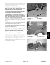
8. Install high tension lead to spark plug when service
is complete.
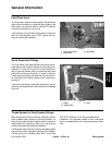
1. Drain valve
2. Elbow fitting
3. Jam nut
4. Agitation tube
Figure 5
3
3
1
2
4
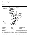
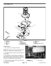
1. Paint tank
2. O–ring
3. Lid flange
4. Strainer
5. Lid
6. Screw (8 used)
Figure 6
2
3
4
1
5
6
10 to 12 in–lb
(1.1 to 1.4 N–m)
Paint
System


