Line Painter 1200Page 5 – 22Paint System
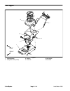
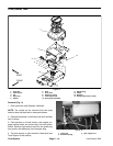
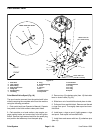
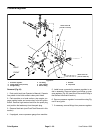
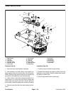
Pressure Regulator
1. Pressure regulator
2. Flange head screw (2 used)
3. Straight fitting
4. Tee fitting
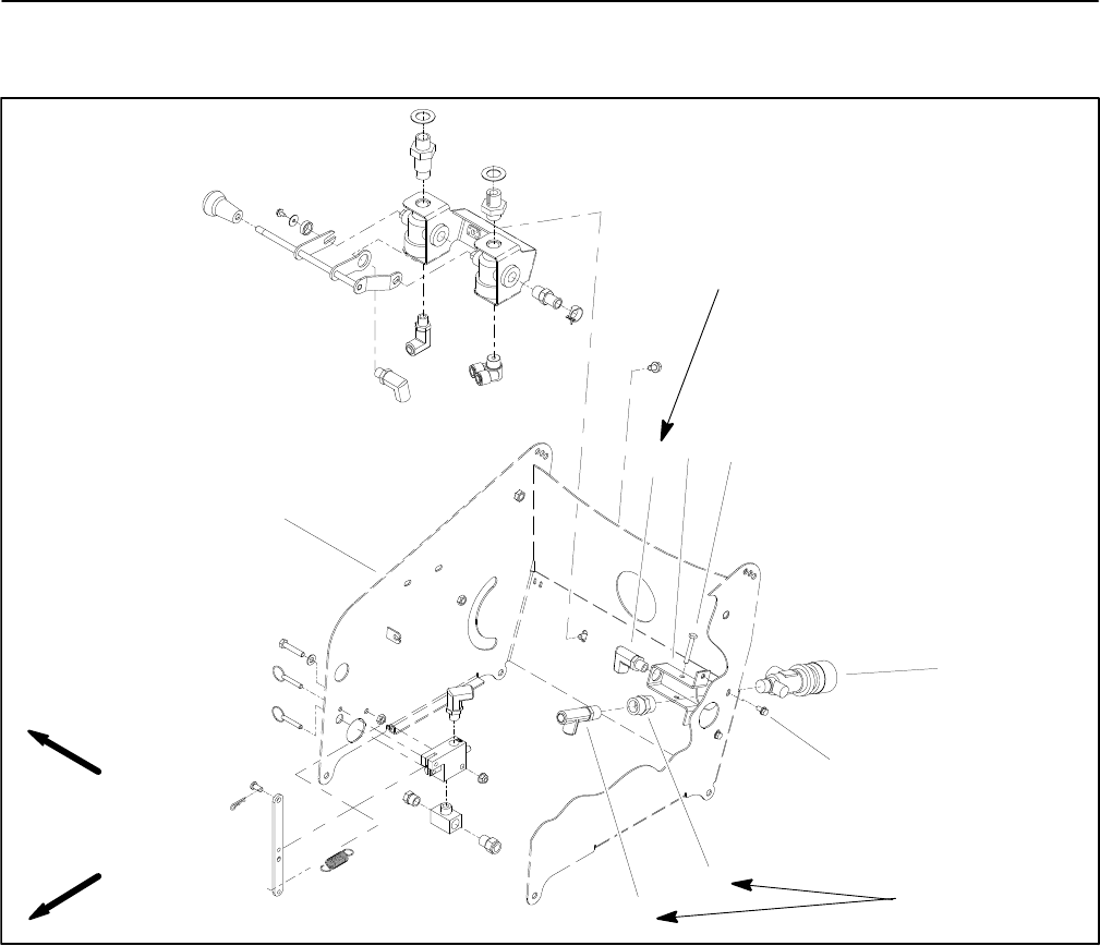
5. Tank support
6. Elbow fitting
7. Bracket
8. Cap screw
Figure 22
FRONT
RIGHT
2
3
4
1
5
6
7
8
144 to 156 in–lb
(16.3 to 17.6 N–m)
120 to 132 in–lb
(13.6 to 14.9 N–m)
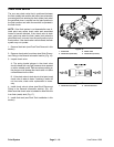
Removal (Fig. 22)
1. Drain paint tank (see Operator’s Manual). Operate
line painter in the flush mode to clean paint tubes.
2. Park machine on a level surface, stop engine, en-
gage parking brake and remove key from the ignition
switch. Remove high tension lead from the spark plug
and position the lead away from the spark plug.
3. Remove flush tank (see Flush Tank Removal in this
section).
4. If equipped, remove pressure gauge from machine.
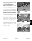
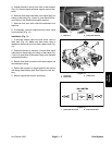
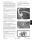
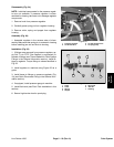
5. Label hoses connected to pressure regulator to as-
sist in assembly. Remove hoses from fittings on pres-
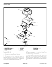
sure regulator (Fig. 23) (see Quick Disconnect Fitting in
the General Information section).
6. Remove pressure regulator from machine using Fig-
ure 22 as a guide.
7. If necessary, remove fittings from pressure regulator.


