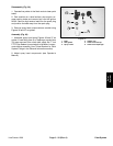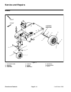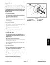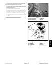
Removal (Fig. 4)
1. Park machine on a level surface, stop engine, en-
gage parking brake and remove key from the ignition
switch. Remove high tension lead from the spark plug
and position the lead away from the spark plug.
2. Raise machine so that wheel to be removed is off the
ground. Support machine to prevent it from shifting dur
-
ing wheel removal.
3. To remove front wheel:
A. Remove lock nut (item 5) and cap screw (item 3)
that secure wheel to castor fork.
B. Slide wheel from castor fork.
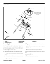
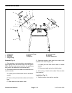
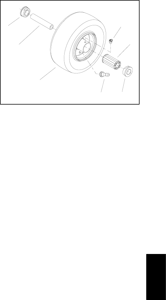
C. Remove front wheel bushing and bearings as
needed (Fig. 5).
4. To remove rear wheel:
A. Remove e–ring (item 6) and washer (item 7) that
secure wheel to transaxle shaft.
B. Slide wheel from transaxle shaft.
C. Locate and retrieve square key (item 9).
Installation (Fig. 4)
1. To install front wheel:
A. If front wheel bushing and bearings were re-
moved, install bushing and bearings to wheel as-
sembly (Fig. 5).
B. Position front wheel to castor fork.
C. Install cap screw (item 3) and lock nut (item 5) to
secure wheel to castor fork.
D. Lubricate grease fitting on front wheel (see Oper-
ator’s Manual).
2. To install rear wheel:
A. Apply antiseize lubricant to transaxle shaft. Posi-
tion square key (item 9) in transaxle slot.
B. Slide wheel onto transaxle shaft.
C. Secure wheel to transaxle shaft with washer
(item 7) and e–ring (item 6).
3. Carefully, lower machine to ground.
4. Secure high tension lead to spark plug.
1
2
3
4
5
6
1
Figure 5
1. Outside bearing
4. Grease fitting
2. Bushing
5. Bearing
3. Rim and tire assembly
6. Valve stem
Chassis and
Controls
Line Painter 1200 Page 6 – 7 Chassis and Controls


