Line Painter 1200 Page 5 – 17 Paint System
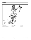
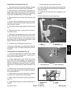
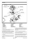
5. Unhook extension spring from hole in tank support
(Fig. 12). Remove spring and tank support rod from ma-
chine.
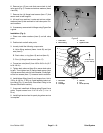
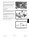
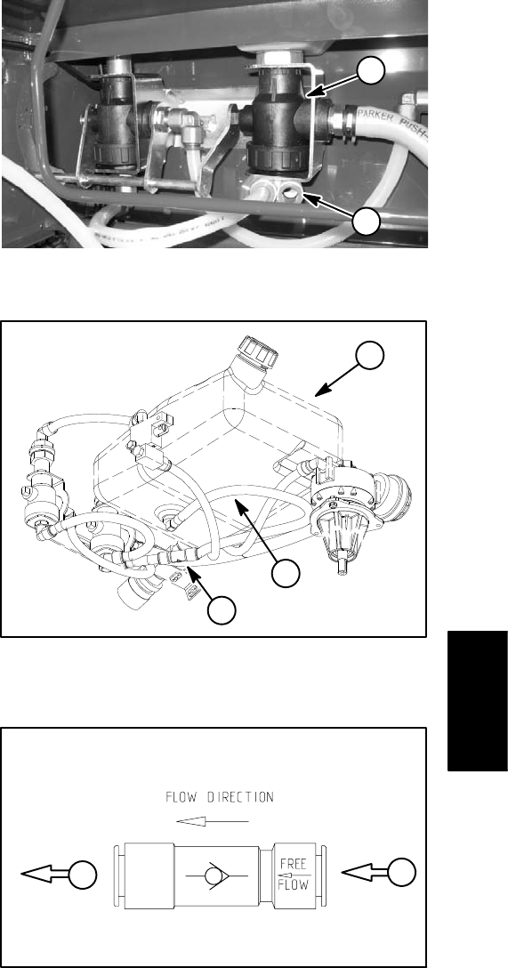
6. Remove flush tank outlet tube from elbow fitting on
bottom of ball valve (Fig. 13 and 14) (see Quick Discon-
nect Fitting in the General Information section).
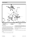
7. Remove flush tank with outlet tube attached from
machine.
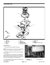
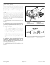
8. If necessary, remove outlet tube and check valve
from flush tank (Fig. 14).
Installation (Fig. 11)
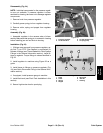
1. If removed, attach outlet tube and check valve to
flush tank (Fig. 14). Make sure that check valve is
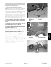
installed to allow free flow from flush (water) tank (Fig.
15).
2. Position flush tank to machine. Connect flush valve
outlet tube to elbow fitting on bottom of ball valve (Fig.
13 and 14) (see Quick Disconnect Fitting in the General
Information section).
3. Secure flush tank to machine with tank support rod
and extension spring.
4. Return tank support to upright position and secure
with flange head screws (see Tank Support in this sec-
tion).
5. Secure high tension lead to spark plug.
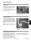
1. Ball valve 2. Outlet tube location
Figure 13
1
2
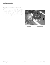
1. Flush tank
2. Outlet tube
3. Check valve
Figure 14
1
2
3
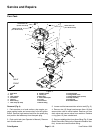
Figure 15
1
2
1. Outlet tube from tank 2. Tube to ball valve
Paint
System


