


7
1600XP Series Installation and Operation Manual
Installation Precautions
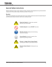
NOTICE
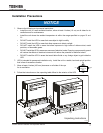
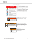
Observe the following environmental restrictions:1.
Install the unit in a well-ventilated location; allow at least 4 inches (10 cm) on all sides for air •
ventilation and for maintenance.
Install the unit where the ambient temperature is within the range specied on• pages 20 and
23.
DO NOT install the UPS in areas that are subject to high humidity.•
DO NOT install the UPS in areas that allow exposure to direct sunlight.•
DO NOT install the UPS in areas that allow exposure to high levels of airborne dust, metal •
particles, or ammable gases.
DO NOT install the UPS in areas near sources of electrical noise. Ensuring a proper earth • ground
will reduce the effects of electrical noise and will reduce the potential for electrical shock.
DO NOT install the UPS in areas that would allow uids or any foreign object to get inside the •
UPS.
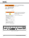
UPS is intended for permanent installation only. Install the unit in a stable, level and upright position 2.
that is free of excessive vibration.
Allow at least 4 inches (100 mm) clearance on all sides of the ups 3.
for air ventilation.
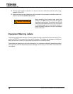
Follow the instructions on the unpacking label afxed to the exterior of the UPS. 4.
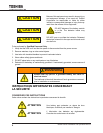
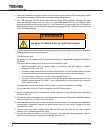
WARNING
This unit contains sealed lead acid batteries.
Lack of preventative maintenance could result
in batteries exploding and emitting gasses and/or
flame. Annual preventative maintenance must be
performed by an authorized, trained technician.
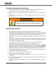
WARNING
CRITICAL FUSE SIZING
Incorrect fuse replacement size
may result in fire or inadequate
equipment protection.
Replace only with same type
and rating of fuse.
49455 SHEET
C AUTIO N/
ATTEN TIO N
Do not disconne ct
wh i le un i t is
o perating
on battery power.
Nes pas debrancher
sous cha rge.
48524 SHEET
Risk of electric shock. Do not remove cover.
. Refer servicing to qualified service personnel.
NO USER SERVICEABLE PARTS
IN SID E
To reduce the risk of fire or electric shock, install in a temperature and
humidity controlled indoor area free of conductive contaminants.
En cas utilisation en atmosphere controlee. Consulter la notice technique.
Note: Service personnel only.
Hazardous live parts inside the UPS are energized from the battery supply
even when the input AC power is disconnected.
Capacitors store hazardous energy. Do not remove cover until 5 minutes
after disconnecting all sources of supply.
Battery backup time, which was factory-set at a predetermined level,
decreases gradually between service periods. The batteries should be
replaced every three years after the last servicing, the date of which is
written on the ID plate located on the rear side of the UPS unit, or in the
boxes below.
Date of last battery charge:
WARNING
CAUTION
Do not insert ba ttery trays with the power off !
This unit is de s igne d for ho t c ha nge a ble ba tt e r ie s !
Whe n i ns t a llin g ba tt e r ie s , the U PS m us t be in the
online or bypass mode. Contact Toshiba
Intern ational Corporation for further details.
60412
PN 51727
EXTERNAL BATTERY CABINET
The battery cabinet must have
a nominal battery voltage of
288VDC.
WARNING
DANGER/ATTENTION
Risk of electrical shock. Do not touch uninsulated
battery terminals. Batteries should be serviced by
qualified service representative only. Miswiring of
battery could result in electrcal shock and/or fire.
Risque de choc electrique. Le circuit des batteries
nest pas esolede secteur. Les cosses des batteries
peuvent presenter une tension dangereuse part
rapport a la terre. Verifier avant de toucher.
DANGER
Battery fuse is always
live. Risk of electrical
shock. Check fuse
voltage and disconnect
external batteries
before changing fuse.
48518 SHEET
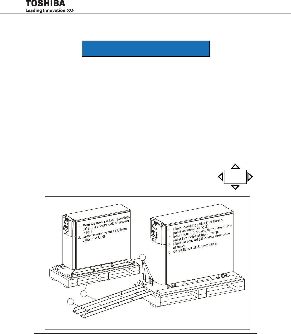
fig 1
fig 2
1
2
3
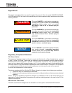
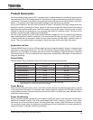
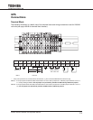
Unpacking Instructions
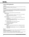
P/N 48537
TYPEFORM
OUTPUT
MFD. IN U.S.A. FROM FOREIGN AND DOMESTIC COMPONENTS
HOUSTON, TEXAS
UNINTERRUPTIBLE POWER SUPPLY
INPUT
SERIAL NO.
PN 60381
LISTED
POWER
SUPPLY
27E5
C US
EPO
14
15
16
17
EPO1
EPO2
REMOTE
REM O TE
1
L1
L2 G
X1 X2
208V
120V
120V
20 8/ 2 40 V
OUTPUT
INPUT
N
X3
G
208V
USE COPPER 90 CONDUCTORS ONLY. REFER TO INSTRUCTION MANUAL REGARDING TIGHTENING TORQUE OF TERMINAL BLOCKS. FACTORY WIRED FOR 208V INPUT.
C OM
2
3
4
5
6 7
8
11
12
13
240V
240V
REMOTE
JUMPER SELECTION
50802
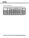
Right
Minimum 4 in.
(100 mm)
Clearance all
sides
Front
Rear
Left