71
1600XP Series Installation and Operation Manual
Optional MB (Maintenance Bypass) Units
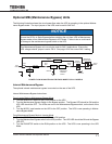
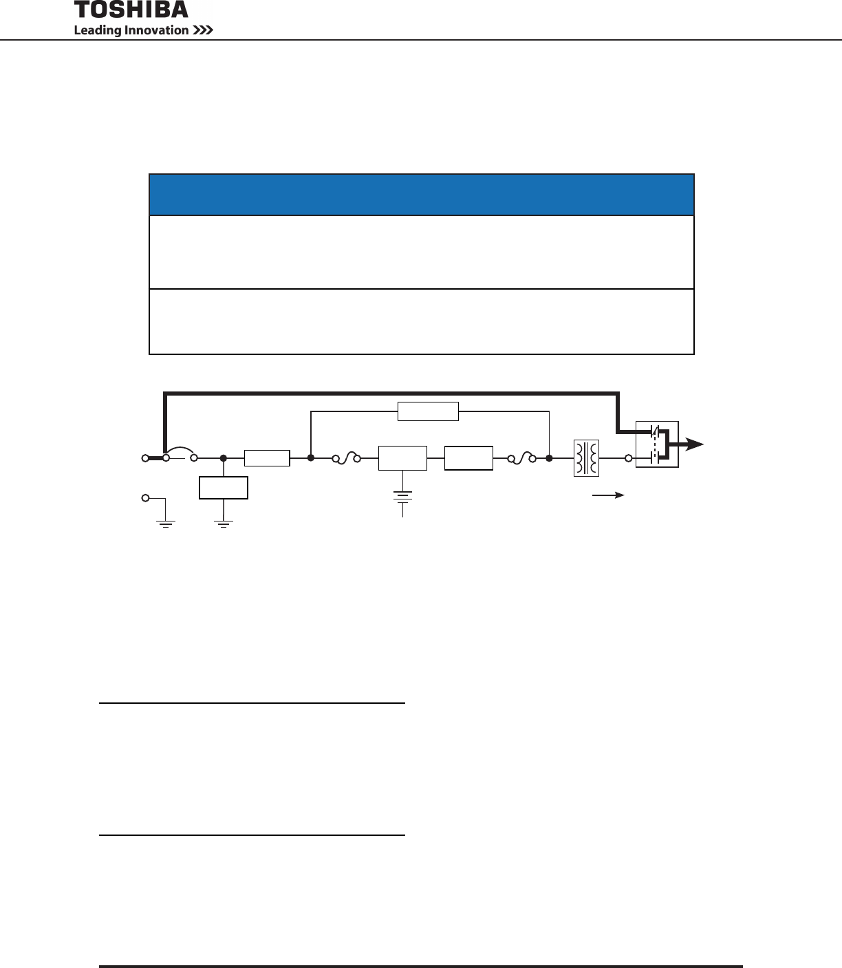
The following illustration shows the circuit power ow when the UPS is operating in the optional Mainte-
nance Bypass mode. The input jumper on the UPS must be set for 240 VAC.
NOTICE
Ensure the UPS is in Static Bypass before switching the unit from UPS to Maintenance
Bypass mode or from Maintenance Bypass to UPS mode. Failure to do so could result
in damage to the maintenance bypass switch or the UPS.
This Maintenance Bypass unit can only be used for 240 V applications. Ensure the
UPS voltage selector jumper is set to 240 V. See page 13 for the correct 240 V setting.
Internal Maintenance Bypass
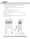
The optional internal maintenance bypass is mounted on the rear of the UPS.
Internal Maintenance Bypass Instructions:
From Inverter Mode to Maintenance Bypass Mode
Turn the RUN/STOP switch to the STOP position on the UPS.1.
Turn the Maintenance Bypass Switch to the Bypass position. The Bypass LED should be ON and the 2.
UPS LED should be OFF. The LEDs are next to the Maintenance Bypass switch, on the back of the
UPS.
Turn the MCCB input breaker on the UPS to the OFF position. The UPS is now operating in Mainte-3.
nance Bypass Mode.
From Maintenance Bypass Mode to Inverter Mode
Turn the MCCB input breaker on the UPS to the ON position.1.
Turn the Maintenance Bypass switch to the UPS position. The UPS LED should be ON and the Bypass 2.
LED OFF.
Turn the RUN/STOP switch to the RUN position on the UPS. The UPS is now operating in the UPS 3.
Mode.
POWER FLOW IN MAINTENANCE BYPASS MODE FOR ALL MODELS
Output
Power
Line Filter Inverter
*Static Switch
Isolation
Transformer
Input
Power
Input
Fuse
Power Flow
Bypass
* Switches are
solid state
devices.
MCCB
Output
Fuse
Surge
Absorber
Batteries
+
–
Rectier/
Chopper
Maintenance
Bypass Switch
Negative
Bus


