40
1600XP Series Installation and Operation Manual
Screen Tab: Monitor
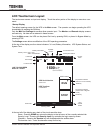
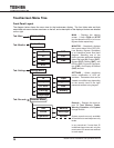
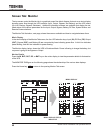
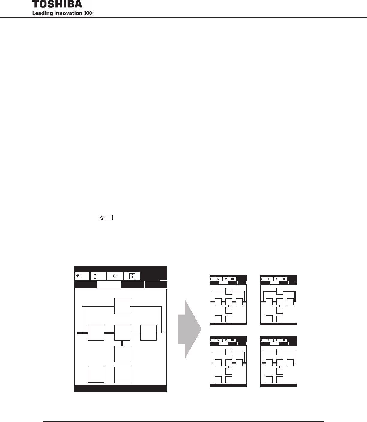
The top screen under the Monitor tab is a graphical power ow block diagram that acts as a mimic display
showing power ow through the UPS sections (Input, Output, Bypass, and Battery) and the UPS status
(On-Line, Backup, Bypass, Shutdown). Additional information screens are available that display the de-
tailed status of the various parameters for the Input, Output, Bypass, Battery, DC Bus, System Status, and
Remote Communications.
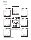
The Monitor Tab illustration, next page, shows the screens available and how to navigate between them.
Mimic Display
In the mimic display of the Monitor Tab screen, the four UPS selection keys, Input (IN), DC Bus, (DC) Output
(OUT), Bypass (BYP), and Battery (0) are connected by lines indicating power ow. A thick line indicates
power owing, and thin line indicates no power owing.
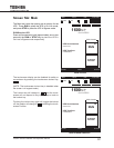
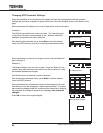
The Monitor display, below, shows the UPS in Shutdown Mode: Power is owing to charge the battery, but
no power is going to the Bypass or Output.
Monitor Details
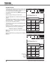
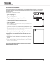
Press the IN, BYP, OUT, DC, or BAT key on the mimic display to view the parameter details for that section
of the UPS.
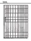
The MONITOR TAB gure on the following page shows the relationship of the various data displays.
Press the Home key,
Home
, to return to the opening Monitor Tab screen.
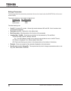
MIMIC DISPLAY STATUS
INDICATOR
On-Line
DVCOH
ASYN
Main Monitor Settings Records
12:35 PMINV
HOME
USR
BYP
BAT
D&E
IN OUTDC
C&C
MIMIC DISPLAY
ON-LINE MODE BYPASS MODE
BACKUP MODE OUTPUT SHUTDOWN
MODE
On-Line
Main Monitor Settings Records
12:35 PM
INV
HOME
USR
BYP
BAT
D&E
IN OUTDC
C&C
Bypass
DVCOH
ASYN
Main Monitor Settings Records
12:35 PM
BYP
HOME
USR
BYP
BAT
D&E
IN OUTDC
C&C
Backup
DVCOH
ASYN
Main Monitor Settings Records
12:35 PM
INV
HOME
USR
BYP
BAT
D&E
IN OUTDC
C&C
Shutdown
DVCOH
ASYN
Main Monitor Settings Records
12:35 PM
WRN
HOME
USR
BYP
BAT
D&E
IN OUTDC
C&C
96% 100%
96% 100%
96% 100%
96% 100% 96% 100%


