35
1600XP Series Installation and Operation Manual
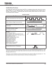
Status Indicators
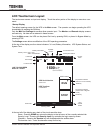
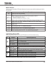
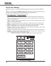
The four top and three bottom UPS status Indicators on the main screen and their meanings are listed in
the table below. .
Indicator Functional Description
96% Shows the current load percentage.
100% / 11’
100% / 9’ 35”
100% / N/A
Battery Information: In On-line and Battery Back-up mode the display alternates between
battery charge percentage and estimated remaining battery runtime in:
Minutes for Runtimes > 10 min.
Minutes and Seconds for Runtimes < 10 min.
In other modes, the display alternates between battery charge percentage and “N/A.”
INV
Shows current UPS Status. Indicator will change as the UPS status changes. For a
detailed listing see page 56.
12:35 PM System Time
DVCOH Fault Description Code - For a detailed listing see 53.
ASYN Warning Description Code - For a detailed listing see page 54.
On-Line Current operating mode of the UPS - For a detailed listing see page 56.
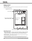
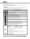
Light Emitting Diodes (LED)
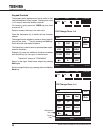
The following table describes the front panel LED behaviors and the associated meaning.
LED Behavior Signicance/Meaning
Green - ON UPS is in On-Line, Backup, or Battery Test mode.
Green - OFF UPS in Bypass mode.
Green - OFF UPS in shutdown mode.
Red - ON One or more faults occurred. See Records: Faults for details.
Red - Flashing Charger overvoltage occurred.
Red - OFF No fault occurred.
Amber - ON
Service Call needed, Less than 6 mo. of Battery Life or Battery Life
End.
Amber - Flashing One or more Warnings occurred. See Records: Warnings for details.
Amber - OFF No Warning (Normal, UPS in operation).
Green - ON Input and Bypass voltage is within specied range.
Green - Flashing Input and Bypass voltage is over specied range.
Green - OFF Input and Bypass voltage is under specied range.
NOTE: On-Line/Fault LEDs - Appear Orange if Green and Red ash concurrently.
AC Input
Warning
On-Line/
Fault


