


70
1600XP Series Installation and Operation Manual
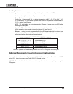
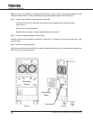
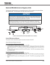
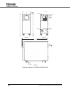
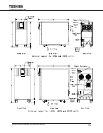
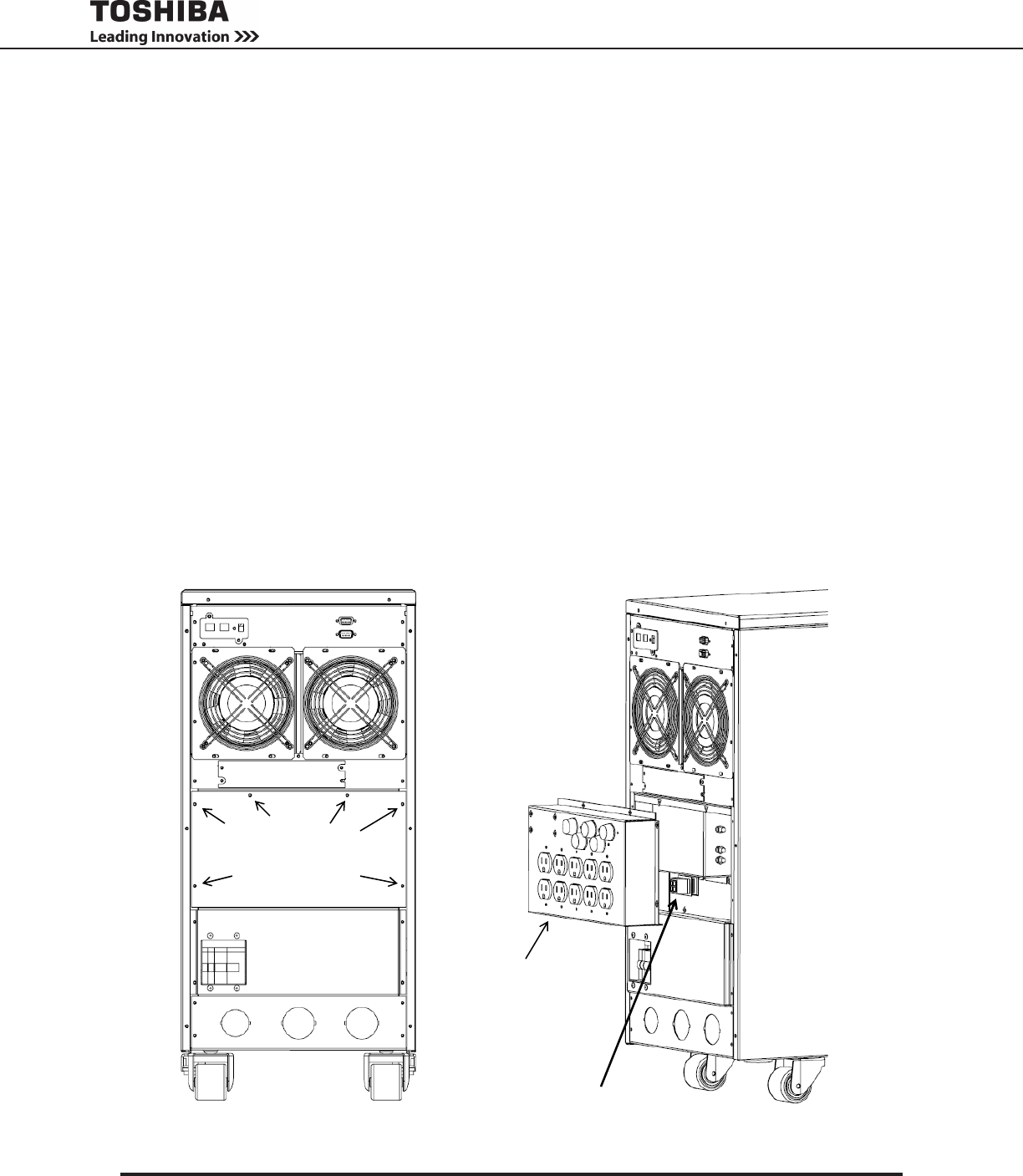
Refer to Figure 1 for location of UPS referenced material. Refer to Figure 2 for material referring to the
receptacle panel module. There are different panels available depending on the UPS typeform.
Step 1: Remove the modular receptacle panel cover plate.
On the rear of the UPS, locate the cover plate for the receptacle panel module interface
(see Figure 1).
Remove the 6 mounting screws.
Remove the cover plate. A square-shaped plug will be exposed.
Step 2: Snap-In Output Receptacle modular panel.
Carefully mate the square-shaped connector on the UPS to its matching counter part on the rear of the
modular panel.
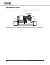
Step 3: Mount the receptacle panel.
Attach the screws removed from the cover plate through the mounting holes of the receptacle panels and
back into the UPS mounting points.
Figure 1 Figure 2