


Series Operation
7–6 445-0089-01-01
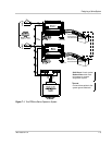
Connecting AC Output Wiring
To connect each PROsine to the load panel:
1. Connect 2-conductor-plus-ground cable to the Line 1 PROsine’s AC Output
line and neutral conductors, and connect the cable’s ground wire to one of the
output ground screws on the PROsine.
2. Run the 2-conductor-plus-ground cable to the load panel and connect:
• The Line 1 conductor to the panel’s Line 1 input breaker
• The neutral to the panel’s neutral bus
• The ground to the panel’s ground bus
3. Repeat steps 2 and 3, connecting the Line 2, neutral, and ground from the Line
2 PROsine to the load panel’s Line 2 input breaker, neutral bus, and ground
bus.
Configuring the Inverter Output Neutral Bonding
Electrical codes require that you unbond the neutral-ground connection of one of
the PROsines. Otherwise when the units are inverting, they will both connect the
neutral to safety ground through a relay. Installation codes stipulate that the
neutral be connected to safety ground in one—and only one—location.
To unbond the neutral in one of the PROsines:
1. Select one PROsine in which to unbond the neutral.
Generally, it does not matter which PROsine you select, but your system may
dictate that one unit in particular be unbonded.
2. Locate and remove the neutral-ground bonding screw at the back of the AC
wiring compartment.
3. Install the screw in the extra hole (identified as the position in which the
neutral is NOT automatically bonded) so it is available for future use if you
change your system.
4. Tighten the screw so it will not back out over time.
5. Leave the other PROsine’s neutral-ground bonding screw in the automatic
bonding position.
Connecting the DC Cables
WARNING: Fire hazard
Make sure all DC connections are tight to a torque of 216–240 inch-pounds (24–27Nm).
Loose connections will overheat.