


Product Orientation
2–4 445-0089-01-01
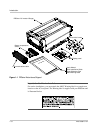
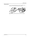
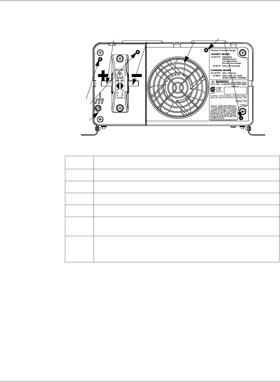
DC End
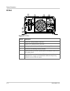
Figure 2-3
DC End
Feature Description
1 Positive DC cabling terminal, 8 mm stud
2 Negative DC cabling terminal, 8 mm stud
3 Cooling fan. (For details, see “Fan Operation” on page 5–3.)
4 Screw holes for mounting accessory modules
5 Chassis ground lug. Provides a ground path for the PROsine chassis to the
DC system ground.
6 Screw holes for mounting the optional DC wiring enclosure. See
“Materials List” on page 1–6 for information about the crimp-on ring
terminals to be used with this option.
c
d
e
f
g
h
B