


Index
445-0089-01-01 IX–3
frozen batteries 6–4
fuse sizes
AC
3–5
DC 3–7
G
gases, battery
precautions
5–7, 7–8
venting 3–22
generators 3–5
GFCI 2–3, 3–7, 3–16
GFCI models, tested 3–8
I
incandescent lights 6–12
induction motors 6–11
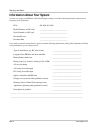
Information about Your System form WA–4
input voltage range 5–6
installation
battery temperature sensor
3–21
choosing a location 3–9
codes 3–2
connecting AC input wires 3–11
connecting AC output wires 3–15
connecting DC cables 3–17
connecting remote shutdown 3–24
designing an installation 3–4
materials 3–3
mounting the display panel 3–20
mounting the PROsine 3–10
output neutral bonding system 3–13
procedures, overview 3–3
tools 3–3
Installer-Only mode, entering 4–2
Internal Error 6–6, 6–9
invert power derating A–6
inverter
purchase date
WA–4
serial number WA–4
inverter efficiency A–5
Inverter LEDs 2–8
AC In 2–6, 2–8
Inverting 2–6, 2–8
Standby 2–6, 2–8
inverter operation, operating limits 5–5
inverter overload operation A–5
Inverter switch
Disable
2–8
Enable 2–8
illustrated 2–6
J
jacks
Battery Temp/Remote
2–2, 3–22, 3–23
Display 2–2
on display panel 2–6, 3–20
Sync, illustrated 2–2
K
kill switch. See remote shutdown.
KKK compliance
A–4
knockouts 2–2
L
LCD panel
backlight
4–11
backlight brightness 4–11
backlight timeout 4–11
described 2–10
illustrated 2–6
temperature display 4–11
LEDs, Charger
Charging
2–6, 2–9
Equalize 2–6, 2–9
Ready 2–9
Standby 2–6, 2–9
LEDs, Inverter
AC In
2–6, 2–8
Inverting 2–6, 2–8
Standby 2–6, 2–8
lights
fluorescent
6–12
incandescent 6–12
load management 1–5
Load Sensing mode 1–3, 5–5
Load Sensing, enabling / disabling 4–7, 4–8
low battery cutout 1–2
low standby battery demand 1–3
M
marine installations
ABYC Warning label
1–8, B–3
DC grounding 3–19
using crimp-on splice connectors 3–11
marine system, illustrated B–3
materials list 3–3
Menu Down button 2–11