


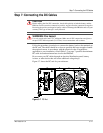

Step 10: Connecting the Remote Shutdown
445-0089-01-01 3–25
Next Steps
At this point, you have installed the PROsine system and are now ready to
configure it.
1. Read the configuration procedures in Chapter 4, “Configuration”.
2. Reconnect the AC shorepower supply.
3. Use the display panel to configure the PROsine.
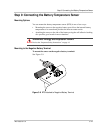
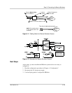
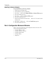
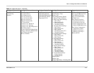
Figure 3-11
Cabling Details for Remote Shutdown Feature
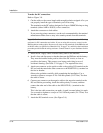
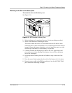
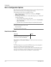
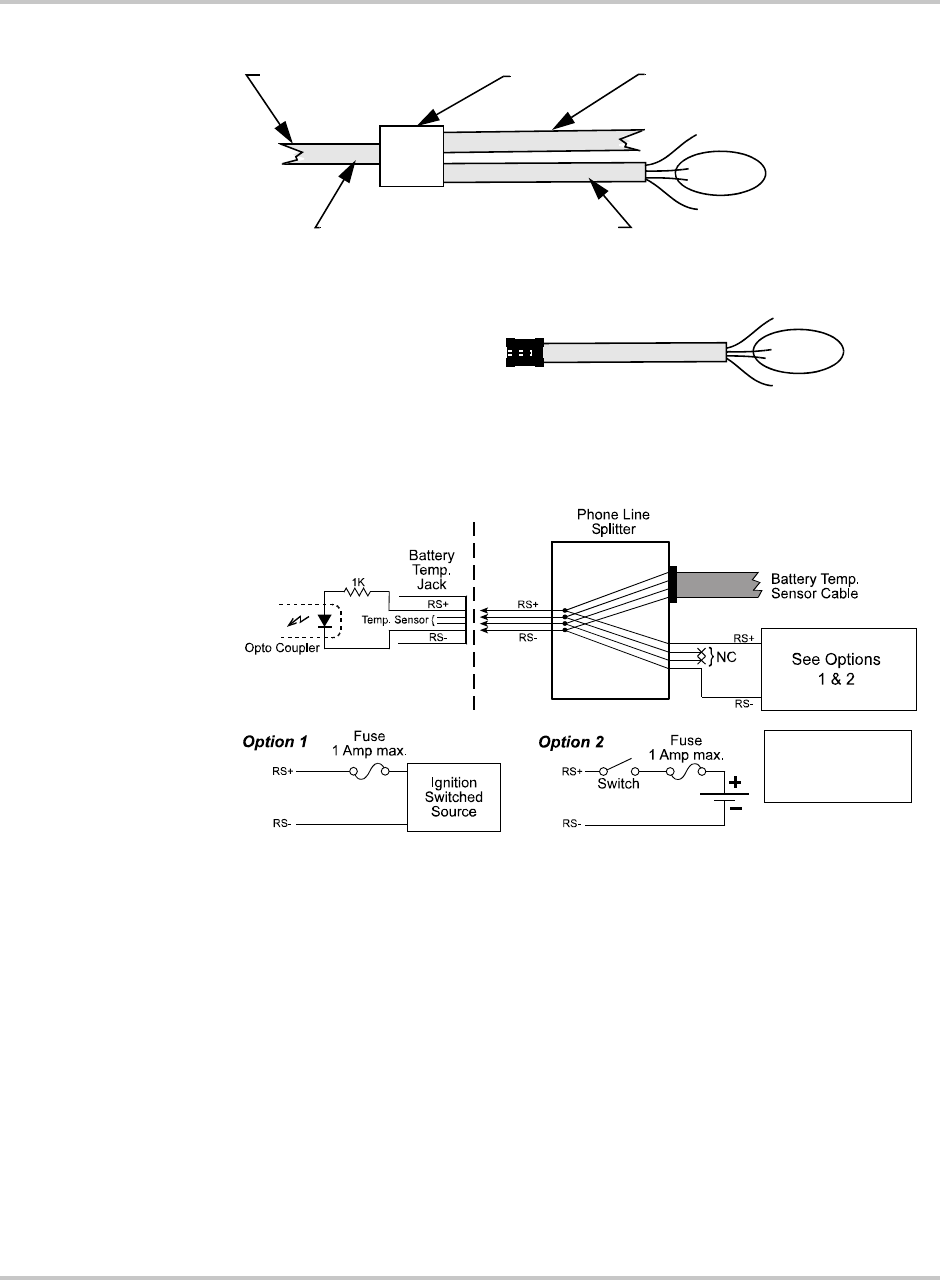
Figure 3-12
Schematic for Remote Shutdown Feature
Do not
use.
RS
+
RS
–
Plug into
Battery Temp
26AWG, 4-conductor telephone cable
1:2 phone
line splitter
Battery Temperature
RS
+
RS
–
Sensor cablejack on PROsine
100 feet max.
10 feet max.
NOTE:
The retaining clip is
on the opposite side of the
Do not
use.
Top view of cable and connector
connector
.
**
Do not connect to
these wires; they are
used for the Battery
Temperature Sensor.
**