Installation
3–4 445-0089-01-01
Step 1: Designing the Installation
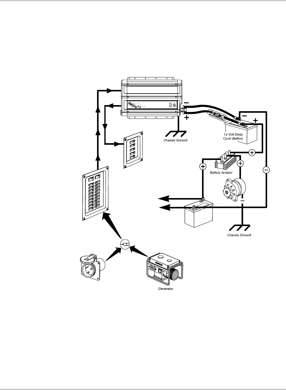
All types of PROsine installations share common components, and these are
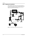
briefly described below. Figure 3-1 shows these components and their relationship
to each other in a typical recreational vehicle or fleet vehicle installation. (For
diagrams of typical residential backup and marine systems as well as series
installations, see Appendix B, “System Diagrams”.)
Figure 3-1
Typical Recreational Vehicle and Fleet Vehicle Installation
l
to engine
{
+
–
DC Fuse /
Disconnect or
Circuit Breaker
AC Load Panel
AC Source Panel
Shorepower
Vehicle Starting
Battery
Automatic or Manual AC
Source Selector Switch


