


2-62 Service Guide
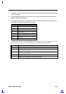
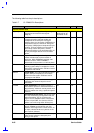
The following table lists the pin descriptions
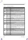
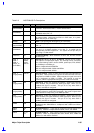
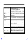
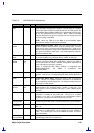
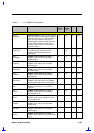
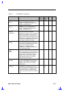
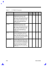
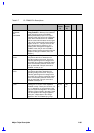
Table 2-7 CL-PD6832 Pin Descriptions
Pin Name Description Pin Number I/O Power
PCI Bus Interface Pins
AD[31:0]
PCI Bus Address Input / Data Input/Outputs:
These pins connect to PCI bus signals
AD[31:0].
4-5, 7-12, 16-20,
22-24, 38-43, 45-
46, 48 49, 51-56
I/O 4
C/BE[3:0]#
PCI Bus Command / Byte Enables: The
command signaling and byte enables are
multiplexed on the same pins. During the
address phase of a transaction, C/BE[3:0]# are
interpreted as the bus commands. During the
data phase, C/BE[3:0]# are interpreted as byte
enables. The byte enables are to be valid for
the entirety of each data phase, and they
indicate which bytes in the 32-bit data path are
to carry meaningful data for the current data
phase.
13, 25, 36, 47 I/O
FRAME#
Cycle Frame: This signal driven by current
master indicates that a bus transaction is
beginning. While FRAME# is asserted, data
transfers continue. When FRAME# is
deasserted, the transaction is in its final phase.
27 I/O
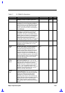
IRDY#
Initiator Ready: This input indicates the
initiating agent's ability to complete the current
data phase of the transaction. IRDY# is used in
conjunction with TRDY#.
29 I/O
TRDY#
Target Ready:
This output indicates the target
agent’s ability to complete the current data
phase of the transaction. TRDY# is used in
conjunction with IRDY#.
30 I/O 4
STOP#
Stop: This output indicates the current target is
requesting the master to stop the current
transaction.
32 I/O 4
LOCK#
Lock Transaction: This signal is used by a
PCI master to perform a locked transaction to a
target memory. LOCK# is used to prevent more
than one master from using a particular system
resource.
58 I/O 4
IDSEL
Initialization Device Select: This input is used
as a chip select during configuration read and
write transactions. This is a point-to-point
signal. The CL-PD6832 must be connected to
its own unique IDSEL line (from the PCI bus
arbiter or one of the high-order AD bus pins).
15 I
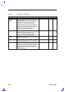
DEVSEL#
Device Select: when actively driven, indicates
that CL-PD6832 has decoded its own PCI
address as the target of the current access. As
an input, indicates whether any device on the
bus has been selected.
31 I/O 4
PERR#
Parity Error: The CL-PD6832 drives this output
active (low) if it detects a data parity error
during a write phase.
33 I/O 4