


Major Chips Description 2-35
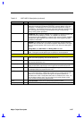
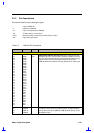
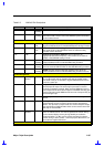
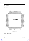
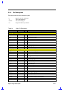
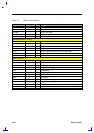
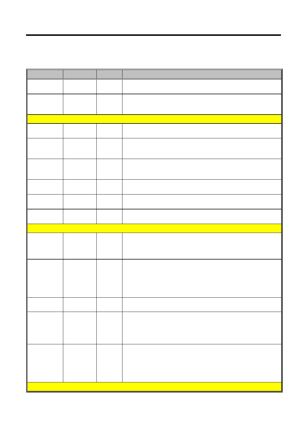
Table 2-3 NM2160 Pin Descriptions
Number Pin name I/O Description
96 B O
(Analog)
BLUE This DAC analog output drives the CRT interface
101 REXT I
(Analog)
DAC Current reference This pin is used as a current reference by
the internal DAC. Please refer to the NM2160 system schematics
for the external circuit
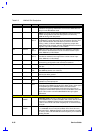
TV interface
79 CSYNC O
T/S
Composite Sync This output is the composite synchronization
signal for RGB-to-NTSC or PAL/SECAM External Analog Encoders
74 NTSC_PAL O
T/S
NTSC/PAL/SECAM Encoding Selection This pin is used to select
the mode NTSC or PAL/SECAM in which the external analog
encoder need to be driven
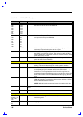
147 FSC O
Sub-Carrier Frequency Selection This pin provides an
appropriate Sub-carrier frequency 1xfsc or 4xfsc to an external
NTSC or PAL/SECAM analog encoder
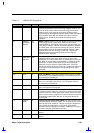
98 R O
(Analog)
RED This DAC analog video red component output is to drive the
external RGB-to-NTSC or PAL/SECAM analog encoders
97 G O
(Analog)
GREEN This DAC analog video green component output is to
drive the external RGB-to-NTSC or PAL/SECAM analog encoders
96 B O
(Analog)
BLUE This DAC analog video blue component is to drive the
external RGB-to-NTSC or PAL/SECAM analog encoders external
Power Management
76 Standby/
Status1
I/O
Standby/Status1 The direction of the pin is controlled by GR18 bit
3. In output mode, this pin indicates the state of standby mode.
The state of this pin is reflected in register CR25 bit 5 and can be
used as a status pin
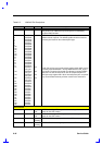
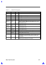
77 Suspend I/O
Suspend This pin can be configured as control Suspend input or
status Suspend output. The active high input mode is used for
controlling hardware Suspend. When asserted NM2160 is forced
into suspend mode where all the inputs are disabled and chip goes
into the low power mode NM2160 will come out of suspend only by
de-asserting this pin
77 Suspend I/O During output mode, this pin will indicate the software suspend
status
75 Activity I/O
Activity This pin when in input mode and asserted indicates the
system activity. A high on this pin can be used to reset internal
timers. This pin when in output mode is a General Purpose Output
pin as defined by CR2F bits 5&4, which can be used to control the
IMI chip for reduced EMI
82 RTC32K/
Status2
I/O
Real Time Clock 32Khz/Status2 This pin is used to feed 32 kHz
from an external source. It is used to generate the refresh timing
for the internal display memory during Standby and software
Suspend modes. 14 MHz can be used to generate the memory
refresh timing in above modes. / General purpose Status bit 3, can
be read from register CR27 bit 0
ZV Interface