


2-10 Service Guide
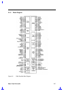
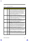
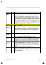
Table 2-2 82371AB Pin Descriptions
Name Type Description
IRDY# I/O
INITIATOR READY. IRDY# indicates PIIX4’s ability, as an Initiator, to complete
the current data phase of the transaction. It is used in conjunction with TRDY#. A
data phase is completed on any clock both IRDY# and TRDY# are sampled
asserted. During a write, IRDY# indicates PIIX4 has valid data present on
AD[31:0]. During a read, it indicates PIIX4 is prepared to latch data. IRDY# is an
input to PIIX4 when PIIX4 is the Target and an output when PIIX4 is an Initiator.
IRDY# remains tri-stated until driven by PIIX4 as a master.
During Reset: High-Z After Reset: High-Z During POS: High-Z
PAR O
CALCULATED PARITY SIGNAL. PAR is “even” parity and is calculated on 36
bits; AD[31:0] plus C/BE[3:0]#. “Even” parity means that the number of “1”s within
the 36 bits plus PAR are counted and the sum is always even. PAR is always
calculated on 36 bits regardless of the valid byte enables. PAR is generated for
address and data phases and is only guaranteed to be valid one PCI clock after
the corresponding address or data phase. PAR is driven and tri-stated identically
to the AD[31:0] lines except that PAR is delayed by exactly one PCI clock. PAR is
an output during the address phase (delayed one clock) for all PIIX4 initiated
transactions. It is also an output during the data phase (delayed one clock) when
PIIX4 is the Initiator of a PCI write transaction, and when it is the Target of a read
transaction.
During Reset: High-Z After Reset: High-Z During POS: High-Z
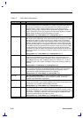
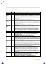
PCIRST# O
PCI RESET. PIIX4 asserts PCIRST# to reset devices that reside on the PCI bus.
PIIX4 asserts PCIRST# during power-up and when a hard reset sequence is
initiated through the RC register. PCIRST# is driven inactive a minimum of 1 ms
after PWROK is driven active. PCIRST# is driven for a minimum of 1 ms when
initiated through the RC register. PCIRST# is driven asynchronously relative to
PCICLK.
During Reset: Low After Reset: High During POS: High
PHOLD# O
PCI HOLD. An active low assertion indicates that PIIX4 desires use of the PCI
Bus. Once the PCI arbiter has asserted PHLDA# to PIIX4, it may not negate it
until PHOLD# is negated by PIIX4. PIIX4 implements the passive release
mechanism by toggling PHOLD# inactive for one PCICLK.
During Reset: High-Z After Reset: High During POS: High
PHLDA# I
PCI HOLD ACKNOWLEDGE. An active low assertion indicates that PIIX4 has
been granted use of the PCI Bus. Once PHLDA# is asserted, it cannot be
negated unless PHOLD# is negated first.
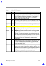
SERR# I/O
SYSTEM ERROR. SERR# can be pulsed active by any PCI device that detects a
system error condition. Upon sampling SERR# active, PIIX4 can be programmed
to generate a non-maskable interrupt (NMI) to the CPU.
During Reset: High-Z After Reset: High-Z During POS: High-Z
STOP# I/O
STOP. STOP# indicates that PIIX4, as a Target, is requesting an initiator to stop
the current transaction. As an Initiator, STOP# causes PIIX4 to stop the current
transaction. STOP# is an output when PIIX4 is a Target and an input when PIIX4
is an Initiator. STOP# is tri-stated from the leading edge of PCIRST#. STOP#
remains tri-stated until driven by PIIX4 as a slave.
During Reset: High-Z After Reset: High-Z During POS: High-Z