


Major Chips Description 2-57
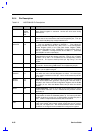
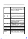
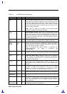
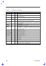
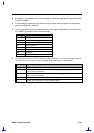
Table 2-6 NS97338VJG Pin Descriptions
Pin No. I/O Description
/RI1
/RI2
68, 60 I
UARTs Ring Indicator. When low, this indicates that a telephone ring
signal has been received by the modem. The /RI signal is a modem
status input whose condition is tested by the CPU by reading bit 6 (RI)
of the Modem Status Register (MSR) for the appropriate serial channel.
Bit 6 is the complement of the RI signal. Bit 2 ( TERI) of the MSR
indicates whether the RI input has changed from low to high since the
previous reading of the MSR.
NOTE:
When the TERI bit of the MSR is set and Modem Status
interrupts are enabled, an interrupt is generated.
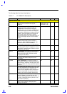
/RTS1
/RTS2
72, 64 O
UARTs Request to Send. When low, this output indicates to the
modem or data set that the UART is ready to exchange data. The RTS
signal can be set to an active low by programming bit 1 (RTS) of the
Modem Control Register to a high level. A Master Reset operation sets
this signal to its inactive (high) state. Loop mode operation holds this
signal to its inactive state.
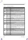
SIN1
SIN2
73, 65 I
UARTs Serial Input. This input receives composite serial data from
the communications link (peripheral device, modem, or data set).
SIRQ1
SIRQ2
SIRQ4
58,
49,
47
I
System interrupt 1, 2, and 3. This input can be routed to one of the
following output pins: IRQ3-IRQ7, IRQ9-IRQ12. SIRQ12 and SIRQ13
can be also routed to IRQ15. Software configuration determines to
which output pin the input pin is routed to.
SIRQ1 is multiplexed with IRQ15, SRIQ12 is multiplexed with
DRATE1/MSEN1/CS0, and SIRQ3 is multiplexed with
DRV2/PNF/DR23.
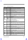
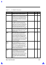
SLCT 80 I
Parallel Port Select. This input is set high by the printer when it is
selected. This pin has a nominal 25 KΩ pull-down resistor attached to
it.
/SLIN 79 I/O
Parallel Port Select Input. When this signal is low, it selects the
printer. This pin is in a tristate condition 10 ns after a 0 is loaded into
the corresponding Control Register bit. The system should pull this pin
high using a 4.7 KΩ resistor.
SOUT1
SOUT2
71,
63
O
UARTs Serial Output. This output sends composite serial data to the
communications link (peripheral device, modem, or data set). The
SOUT signal is set to a marking state (logic 1) after a Master Reset
operation.
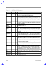
/STB 93 I/O
Parallel Port Data Strobe. This output indicates to the printer that a
valid data is available at the printer port. This pin is in a tristate
condition 10 ns after a 0 is loaded into the corresponding Control
Register bit. The system should pull high using a 4.7 KΩ.
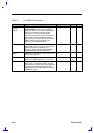
/STEP
(Normal Mode)
38 O
FDC Step. This output signal issues pulses to the disk drive at a
software programmable rate to move the head during a seek operation.
/STEP
(PPM Mode)
79 O
FDC Step. This pin gives an additional step signal in PPM Mode when
PNF = 0.
TC 4 I
Terminal Count. Control signal from the DMA controller to indicate the
termination of a DMA transfer. TC is accepted only when FDACK is
active. TC is active high in PC-AT and Model 30 modes, and active
low in PS/2 mode.
/TRK0
(Normal Mode)
35 I
FDC Track 0. This input indicates the controller that the head of the
selected floppy disk drive is at track zero.