


Major Chips Description 2-53
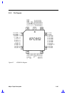
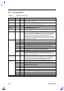
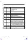
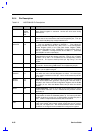
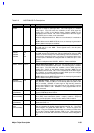
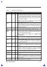
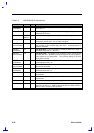
Table 2-6 NS97338VJG Pin Descriptions
Pin No. I/O Description
/CTS1,
/CTS2
72, 64 I
UARTs Clear to Send. When low, this indicates that the modem or
data set is ready to exchange data. The /CTS signal is a modem
status input. The CPU tests the condition of this /CTS signal by
reading bit 4 (CTS) of the Modem Status Register (MSR) for the
appropriate serial channel. Bit 4 is the complement of the CTS signal.
Bit 0 (DCTS) has no effect on the transmitter.
/CTS2 is multiplexed with A13. When it is not selected, it is masked to
“0”.
NOTE:
Whenever the MSR DCTS bit is set, an interrupt is generated if
Modem Status interrupts are enabled.
D7-D0 10-17 I/O
Data. These are bidirectional data lines to the microprocessor. D0 is
the LSB and D7 is the MSB. These signals have a 24 mA (sink)
buffered outputs.
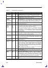
/DACK0
/DACK1
/DACK2
/DACK3
53,
52,
3
49
I
DMA Acknowledge 0, 1, 2, 3. These active low inputs acknowledge
the DMA request and enable the /RD and /WR inputs during a DMA
transfer. It can be used by one of the following: FDC or Parallel Port. If
none of them uses this input pin, it is ignored. If the device which uses
on of this pins is disabled or configured with no DMA, this pin is also
ignored.
DACK3 is multiplexed with DRATE1, MSEN1, /CS0 and SIRQI2.
/DCD1, /DCD2 75, 67 I
UARTs Data Carrier Detect. When low, this indicates that the modem
or data set has detected the data carrier. The /DCD signal is a modem
status input. The CPU tests the condition of this /DCD signal by
reading bit 7 (DCD) of the Modem Status Register (MSR) for the
appropriate serial channel. Bit 7 is the complement of the DCD signal.
Bit 3 (DDCD) of the MSR indicates whether DCD input has changed
state since the previous reading of the MSR.
NOTE:
Whenever the MSR DDCD bit is set, an interrupt is generated if
Modem Status interrupts are enabled.
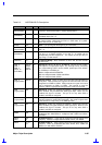
DENSEL
(Normal Mode)
46 O
FDC Density Select. DENSEL indicates that a high FDC density data
rate (500 Kbs, 1 Mbs or 2 Mbs) or a low density data rate (250 or 300
Kbs) is selected. DENSEL is active high for high density (5.25-inch
drives) when IDENT is high, and active low for high density (3.5-inch
drives) when IDENT is low. DENSEL is also programmable via the
Mode command.
DENSEL
(PPM Mode)
76 O
FDC Density Select. This pin offers an additional Density Select
signal in PPM Mode when PNF=0.
/DIR
(Normal Mode)
39 O
FDC Direction. This output determines the direction of the floppy disk
drive (FDD) head movement (active = step-in; inactive = step-out)
during a seek operation. During reads or writes, DIR is inactive.
/DIR
(PPM Mode)
78 O
FDC Direction. This pin offers an additional Direction signal in PPM
Mode when PNF = 0.
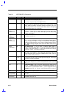
/DR0,
/DR1
(Normal Mode)
42, 43 O
FDC Drive Select 0, 1. These are the decoded drive select outputs
that are controlled by Digital Output Register bits D0, D1. The Drive
Select outputs are gated with DOR bits 4-7. These are active low
outputs. They are encoded with information to control four FDDs when
bit 4 of the Function Enable Register (FER) is set. DR0 exchanges
logical drive values with DR1 when bit 4 of Function Control Register is
set.