


Major Chips Description 2-71
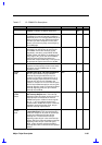
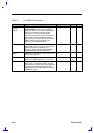
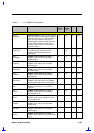
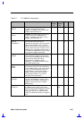
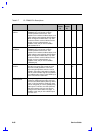
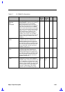
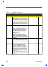
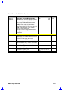
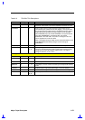
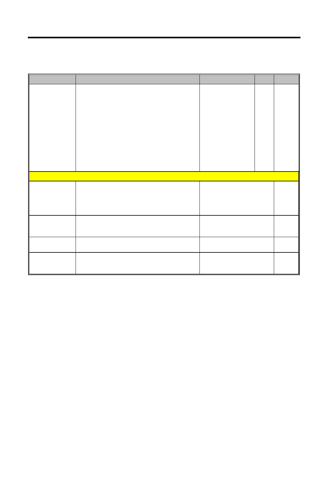
Table 2-7 CL-PD6832 Pin Descriptions
Pin Name Description Pin Number I/O Power
SLATCH/
SMBLCKt
Serial Latch / System Management Bus
Clock: This pin serves as output pin SLATCH
when used with the serial interface of Texas
Instruments' TPS2202AIDF socket power
control chip, and serves as a bidirectional pin
SMBCLK when used with Intel's System
Management Bus used by Maxim's socket
power control chip. This pin is open drain in the
SMB mode of operation. In this mode an
external pull up is required.
This pin is used for configuration information
during hardware reset. Refer to misc Control 3
register bit 2.
130 I/O-
PU
2 or3
Power and Ground Pins
+5V This pin is connected to the system's 5-volt
power supply. In systems where 5 volts is not
available, this pin can be connected to the
system's 3.3-volt supply (but no 5volt
connections to the CL-PD8632 will be allowed).
127 PWR
CORE_VDD This pin provides power to the core circuitry of
the CL-PD6832. This pin must be connected to
the 3.3-volt supply.
134 PWR
CORE_GND All CL-PD6832 ground lines should be
connected to system ground.
26 GND
RING_GND All CL-PD6832 ground lines should be
connected to system ground.
14, 28, 44, 57, 72, 87, 101,
115, 129, 146, 163, 177,
193
GND