


2-18 Service Guide
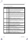
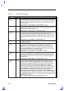
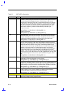
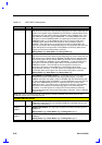
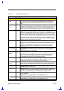
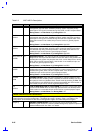
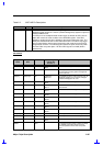
Table 2-2 82371AB Pin Descriptions
Name Type Description
INIT OD
INITIALIZATION. INIT is asserted in response to any one of the following
conditions. When the System Reset bit in the Reset Control Register is reset to
0 and the Reset CPU bit toggles from 0 to 1, PIIX4 initiates a soft reset by
asserting INIT. PIIX4 also asserts INIT if a Shut Down Special cycle is decoded
on the PCI Bus, if the RCIN# signal is asserted, or if a write occurs to Port 92h,
bit 0. When asserted, INIT remains asserted for approximately 64 PCI clocks
before being negated. This signal is active high for Pentium processor and
active-low for Pentium II processor as determined by CONFIG1 signal.
Pentium Processor:
During Reset: Low After Reset: Low During POS: Low
Pentium II Processor:
During Reset: High After Reset: High During POS: High
INTR OD
CPU INTERRUPT. INTR is driven by PIIX4 to signal the CPU that an interrupt
request is pending and needs to be serviced. It is asynchronous with respect to
SYSCLK or PCICLK and is always an output. The interrupt controller must be
programmed following PCIRST# to ensure that INTR is at a known state.
During Reset: Low After Reset: Low During POS: Low
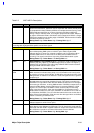
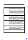
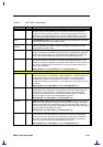
NMI OD
NON-MASKABLE INTERRUPT. NMI is used to force a nonmaskable interrupt to
the CPU. PIIX4 generates an NMI when either SERR# or IOCHK# is asserted,
depending on how the NMI Status and Control Register is programmed. The CPU
detects an NMI when it detects a rising edge on NMI. After the NMI interrupt
routine processes the interrupt, the NMI status bits in the NMI Status and Control
Register are cleared by software. The NMI interrupt routine must read this
register to determine the source of the interrupt. The NMI is reset by setting the
corresponding NMI source enable/disable bit in the NMI Status and Control
Register. To enable NMI interrupts, the two NMI enable/disable bits in the register
must be set to 0, and the NMI mask bit in the NMI Enable/Disable and Real Time
Clock Address Register must be set to 0. Upon PCIRST#, this signal is driven
low.
During Reset: Low After Reset: Low During POS: Low
SLP# OD
SLEEP. This signal is output to the Pentium II processor in order to put it into
Sleep state. For Pentium processor it is a No Connect.
During Reset: High-Z After Reset: High-Z During POS: High-Z
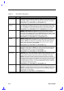
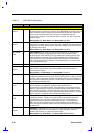
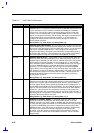
SMI# OD
SYSTEM MANAGEMENT INTERRUPT. SMI# is an active low synchronous
output that is asserted by PIIX4 in response to one of many enabled hardware or
software events. The CPU recognizes the falling edge of SMI# as the highest
priority interrupt in the system, with the exception of INIT, CPURST, and FLUSH.
During Reset: High-Z After Reset: High-Z During POS: High-Z
STPCLK# OD
STOP CLOCK. STPCLK# is an active low synchronous output that is asserted by
PIIX4 in response to one of many hardware or software events. STPCLK#
connects directly to the CPU and is synchronous to PCICLK.
During Reset: High-Z After Reset: High-Z During POS: High-Z
CLOCKING SIGNALS
CLK48 I
48-MHZ CLOCK. 48-MHz clock used by the internal USB host controller. This
signal may be stopped during suspend modes.