


2-16 Service Guide
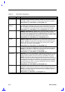
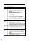
Table 2-2 82371AB Pin Descriptions
Name Type Description
INTERRUPT CONTROLLER/APIC SIGNALS
APICACK#/
GPO12
O
APIC ACKNOWLEDGE. This active low output signal is asserted by PIIX4 after
its internal buffers are flushed in response to the APICREQ# signal. When the I/O
APIC samples this signal asserted it knows that PIIX4’s buffers are flushed and
that it can proceed to send the APIC interrupt. The APICACK# output is
synchronous to PCICLK. If the external APIC is not used, then this is a general-
purpose output.
During Reset: High After Reset: High During POS: High/GPO
APICCS#/
GPO13
O
APIC CHIP SELECT. This active low output signal is asserted when the APIC
Chip Select is enabled and a PCI originated cycle is positively decoded within the
programmed I/O APIC address space. If the external APIC is not used, this pin is
a general-purpose output.
During Reset: High After Reset: High During POS: High/GPO
APICREQ#/
GPI5
I
APIC REQUEST. This active low input signal is asserted by an external APIC
device prior to sending an interrupt over the APIC serial bus. When PIIX4
samples this pin active it will flush its F-type DMA buffers pointing towards PCI.
Once the buffers are flushed, PIIX4 asserts APICACK# which indicates to the
external APIC that it can proceed to send the APIC interrupt. The APICREQ#
input must be synchronous to PCICLK. If the external APIC is not used, this pin
is a general-purpose input.
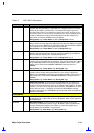
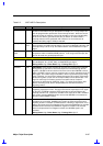
INTR OD
INTERRUPT. See CPU Interface Signals.
IRQ0/
GPO14
O
INTERRUPT REQUEST 0. This output reflects the state of the internal IRQ0
signal from the system timer. If the external APIC is not used, this pin is a
general-purpose output.
During Reset: Low After Reset: Low During POS: IRQ0/GPO
IRQ1 I
INTERRUPT REQUEST 1. IRQ1 is always edge triggered and can not be
modified by software to level sensitive. A low to high transition on IRQ1 is latched
by PIIX4. IRQ1 must remain asserted until after the interrupt is acknowledged. If
the input goes inactive before this time, a default IRQ7 is reported in response to
the interrupt acknowledge cycle.
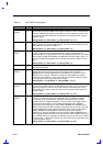
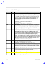
IRQ 3:7, 9:11,
14:15
I
INTERRUPT REQUESTS 3:7, 9:11, 14:15. The IRQ signals provide both system
board components and ISA Bus I/O devices with a mechanism for
asynchronously interrupting the CPU. These interrupts may be programmed for
either an edge sensitive or a high level sensitive assertion mode. Edge sensitive
is the default configuration. An active IRQ input must remain asserted until after
the interrupt is acknowledged. If the input goes inactive before this time, a default
IRQ7 is reported in response to the interrupt acknowledge cycle.
IRQ8#/
GPI6
I/O
IRQ 8#. IRQ8# is always an active low edge triggered interrupt and can not be
modified by software. IRQ8# must remain asserted until after the interrupt is
acknowledged. If the input goes inactive before this time, a default IRQ7 is
reported in response to the interrupt acknowledge cycle. If using the internal
RTC, then this can be programmed as a general-purpose input. enabling an
APIC, this signal becomes an output and must not be programmed as a general
purpose input.
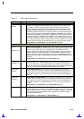
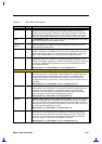
IRQ9OUT#/
GPO29
O
IRQ9OUT#. IRQ9OUT# is used to route the internally generated SCI and SMBus
interrupts out of the PIIX4 for connection to an external IO APIC. If APIC is
disabled, this signal pin is a General Purpose Output.
During Reset: High After Reset: High During POS: IRQ9OUT#/GPO