


4-4 Service Guide
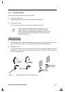
Connectors mentioned in the following procedures are assumed to
be no-lock connectors unless specified otherwise.
4.1.3 Disassembly Sequence
The disassembly procedure described in this manual is divided into eight major sections:
•
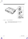
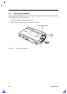
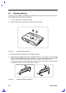
Section 4.2: Removing the module
•
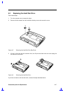
Section 4.3: Replacing the hard disk drive
•
Section 4.4: Replacing memory
•
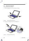
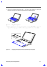
Section 4.5: Removing the keyboard
•
Section 4.6: Replacing the CPU
•
Section 4.7: Removing the display
•
Section 4.8: Disassembling the inside assembly frame
•
Section 4.9: Disassembling the display
The following table lists the components that need to be removed during servicing. For example, if
you want to remove the motherboard, you must first remove the keyboard, then disassemble the
inside assembly frame in that order.
Table 4-1 Guide to Disassembly Sequence
Service Item Prerequisite
Install CPU Remove the keyboard.
Remove the keyboard Remove two speaker covers on both sides and one center hinge
cover.
Remove or replace the hard disk drive Remove the hard disk drive bay cover.
Install additional memory Remove the SIMM door.
Remove the touchpad 1. Remove the keyboard.
2. Remove the LCD display module.
3. Remove the upper unit of lower case.
Replace the LCD Remove the LCD display module.
Remove the motherboard for service
or replacement
1. Remove the keyboard.
2. Remove the LCD display module.
3. Remove the lower unit of lower case.