


Major Chips Description 2-75
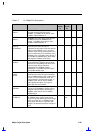
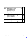
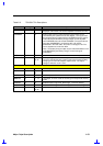
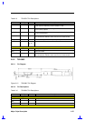
Table 2-9 T62.055.C Pin Descriptions
Pin Name Pin Type Pin No. Descriptions
BATTLED O 13 This signal is an open collector sink signal to drive LED2. The
LED current is limited by a series resistor of 1KΩ.
BMCVCC O 14 This a 5 volt supply for powering the LEDs. It should not be used
for any other purpose.
ADVDD O 18 This is a 5 volt power line for the analog circuits and display LEDs
on the inverter board.
AUDGND GND 19, 20 This is the return ground for the microphone circuit. It should not
be connected to VGND or other circuit on the inverter board.
MIC_OUT O 21 This is the output of the microphone preamplifier circuit.
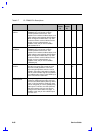
N.C. - 10, 11,
15, 16,
17
Non-connected.
CN3 connector signals
MIC-CON I 1 Microphone input
N.C. - 2 Non-connected.
AUDGND GND 3 This is the return ground for the microphone circuit. It should not
be connected to VGND or other circuit on the inverter board.
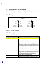
2.9.2 T62.088C
2.9.2.1 Pin Diagram
Figure 2-13 T62.088.C Pin Diagram
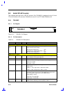
2.9.2.2 Pin Descriptions
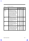
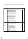
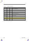
Table 2-10 T62.088.C Pin Descriptions
Pin Name Pin Type Pin No. Descriptions
CN1 connector signals
VOUT1 O 1 Lamp, HV
NC 2
VOUT2 O 3 Lamp, LV
CN2 connector signals