


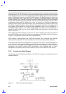
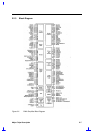

Major Chips Description 2-13
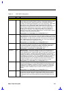
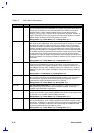
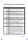
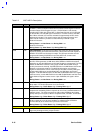
Table 2-2 82371AB Pin Descriptions
Name Type Description
SA[19:0] I/O
SYSTEM ADDRESS[19:0]. These bi-directional address lines define the
selection with the granularity of 1 byte within the 1-Megabyte section of memory
defined by the LA[23:17] address lines. The address lines SA[19:17] that are
coincident with LA[19:17] are defined to have the same values as LA[19:17] for
all memory cycles. For I/O accesses, only SA[15:0] are used, and SA[19:16] are
undefined. SA[19:0] are outputs when PIIX4 owns the ISA Bus. SA[19:0] are
inputs when an external ISA Master owns the ISA Bus.
During Reset: High-Z After Reset: Undefined During POS: Last SA
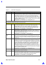
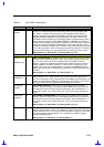
SBHE# I/O
SYSTEM BYTE HIGH ENABLE. SBHE# indicates, when asserted, that a byte is
being transferred on the upper byte (SD[15:8]) of the data bus. SBHE# is negated
during refresh cycles. SBHE# is an output when PIIX4 owns the ISA Bus. SBHE#
is an input when an external ISA master owns the ISA Bus.
During Reset: High-Z After Reset: Undefined During POS: High
SD[15:0] I/O
SYSTEM DATA. SD[15:0] provide the 16-bit data path for devices residing on the
ISA Bus. SD[15:8] correspond to the high order byte and SD[7:0] correspond to
the low order byte. SD[15:0] are undefined during refresh.
During Reset: High-Z After Reset: Undefined During POS: High-Z
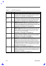
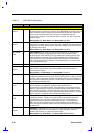
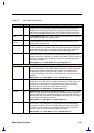
SMEMR# O
STANDARD MEMORY READ. PIIX4 asserts SMEMR# to request an ISA
memory slave to drive data onto the data lines. If the access is below the 1-Mbyte
range (00000000h–000FFFFFh) during DMA compatible, PIIX4 master, or ISA
master cycles, PIIX4 asserts SMEMR#. SMEMR# is a delayed version of
MEMR#.
During Reset: High-Z After Reset: High During POS: High
SMEMW# O
STANDARD MEMORY WRITE. PIIX4 asserts SMEMW# to request an ISA
memory slave to accept data from the data lines. If the access is below the 1-
Mbyte range (00000000h–000FFFFFh) during DMA compatible, PIIX4 master, or
ISA master cycles, PIIX4 asserts SMEMW#. SMEMW# is a delayed version of
MEMW#.
During Reset: High-Z After Reset: High During POS: High
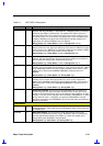
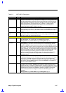
ZEROWS# I
ZERO WAIT STATES. An ISA slave asserts ZEROWS# after its address and
command signals have been decoded to indicate that the current cycle can be
shortened. A 16-bit ISA memory cycle can be reduced to two SYSCLKs. An 8-bit
memory or I/O cycle can be reduced to three SYSCLKs. ZEROWS# has no effect
during 16-bit I/O cycles. If IOCHRDY is negated and ZEROWS# is asserted
during the same clock, then ZEROWS# is ignored and wait states are added as a
function of IOCHRDY.
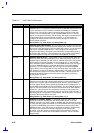
X-BUS INTERFACE
A20GATE I
ADDRESS 20 GATE. This input from the keyboard controller is logically
combined with bit 1 (FAST_A20) of the Port 92 Register, which is then output via
the A20M# signal.
BIOSCS# O
BIOS CHIP SELECT. This chip select is driven active during read or write
accesses to enabled BIOS memory ranges. BIOSCS# is driven combinatorially
from the ISA addresses SA[16:0] and LA[23:17], except during DMA cycles.
During DMA cycles, BIOSCS# is not generated.
During Reset: High After Reset: High During POS: High