


2-24 Service Guide
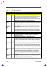
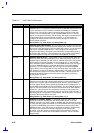
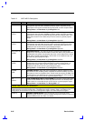
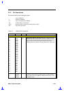
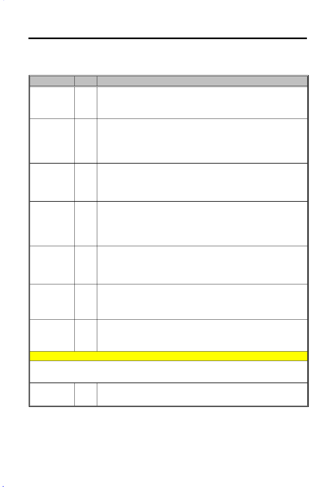
Table 2-2 82371AB Pin Descriptions
Name Type Description
SUSA# O
SUSPEND PLANE A CONTROL. Control signal asserted during power
management suspend states. SUSA# is primarily used to control the primary
power plane. This signal is asserted during POS, STR, and STD suspend states.
During Reset: Low After Reset: High During POS: Low
SUSB#/
GPO15
O
SUSPEND PLANE B CONTROL. Control signal asserted during power
management suspend states. SUSB# is primarily used to control the secondary
power plane. This signal is asserted during STR and STD suspend states. If the
power plane control is not needed, this pin can be used as a general-purpose
output.
During Reset: Low After Reset: High During POS: High/GPO
SUSC#/
GPO16
O
SUSPEND PLANE C CONTROL. Control signal asserted during power
management suspend states, primarily used to control the tertiary power plane.
It is asserted only during STD suspend state. If the power plane control is not
needed, this pin can be used as a general-purpose output.
During Reset: Low After Reset: High During POS: High/GPO
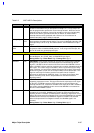
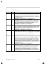
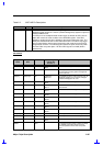
SUS_STAT1#/
GPO20
O
SUSPEND STATUS 1. This signal is typically connected to the Host-to-PCI
bridge and is used to provide information on host clock status. SUS_STAST1# is
asserted when the system may stop the host clock, such as Stop Clock or during
POS, STR, and STD suspend states. If this function is not needed, this pin can
be used as a general-purpose output.
During Reset: Low After Reset: High During POS: Low/GPO
SUS_STAT2#/
GPO21
O
SUSPEND STATUS 2. This signal will typically connect to other system
peripherals and is used to provide information on system suspend state. It is
asserted during POS, STR, and STD suspend states. If this function is not
needed, this pin can be used as a general-purpose output.
During Reset: Low After Reset: High During POS: Low/GPO
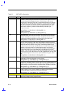
THRM#/
GPI8
I
THERMAL DETECT. Active low signal generated by external hardware to start
the Hardware Clock Throttling mode. If enabled, the external hardware can force
the system to enter into Hardware Clock Throttle mode by asserting THRM#. This
causes PIIX4 to cycle STPCLK# at a preset programmable rate. If this function is
not needed, this pin can be used as a general-purpose input.
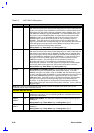
ZZ/
GPO19
O
LOW-POWER MODE FOR L2 CACHE SRAM. This signal is used to power down
a cache’s data SRAMs when the clock logic places the CPU into the Stop Clock.
If this function is not needed, this pin can be used as a general-purpose output.
During Reset: Low After Reset: Low During POS: Low
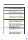
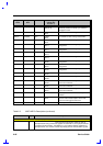
GENERAL PURPOSE INPUT AND OUTPUT SIGNALS
Some of the General Purpose Input and Output signals are multiplexed with other PIIX4 signals. The usage
is determined by the system configuration. The default pin usage is shown in Table 1 and Table 2. The
configuration can be selected via the General Configuration register and X-Bus Chip Select register.
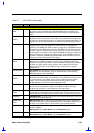
GPI[21:0] I
GENERAL PURPOSE INPUTS.
These input signals can be monitored via the
GPIREG register located in Function 3 (Power Management) System IO Space at
address PMBase+30h. See Table 1 for details.