


Chapter 9. Dial Plan Terminal Menu
61200266L1-1 ATLAS 810
PLUS
User Manual 9-23
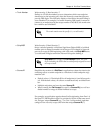
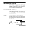
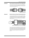
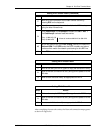
Example 2 Point-to-Point Connection Dial Plan Configuration
In this example, ATLAS A operates as the network while ATLAS B termi-
nates the network. That is, ATLAS A emulates the network and its PRI inter-
face acts as the User termination. The PRI interface of ATLAS B acts as the
Network termination (see Figure 9-4).
Figure 9-4. Point-to-Point
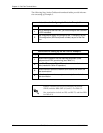
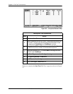
Example 3 Remote Access and Video Conferencing Dial Plan
A corporate office has T1 RBS service for voice but wants to add a PRI for
video conferencing and remote access. The office would like to use the PRI
for all functions, but it still wants to use the incoming BRI to supply added
bandwidth. The office wants to provide BRI lines to the video equipment,
provide a PRI to the remote access server (RAS), and send a T1 RBS to the
PBX (see Figure 9-5).
Figure 9-5. Remote Access and Video Conferencing Setup
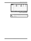
For this example, the User termination BRI lines (D, E, F) each have a specific
phone number. The PRI serving the RAS has an 8-number hunt group, and
the T1 to the PBX uses DID. Assume that all calls originating from the PBX
to 1-900 numbers are restricted. Also, assume that the Network termination
BRI lines (A, B, C) only allow outgoing calls to other local corporate offices
for video conferencing. The numbers fall in the range of 888-0100 to
888-0120.
USER BRI
USER BRI
USER DSX T1 to PBX
BRI USER
BRI USER
T1 from PBX USER
ATLAS A
ATLAS B
User
Term
PRI
Network
Te r m
Interface
Network
ATLAS 810
PLUS
PRI-A
BRI-A
BRI-B
BRI-C
Video Conf.
RAS
PBX
T1-A (RBS821-8xxx [x24] xDID)
BRI-D (888-1001)
BRI-E (888-1002)
BRI-F (888-1003)
PRI-B (888-1010 x8)