


61200266L1-1 ATLAS 810
PLUS
User Manual 4-1
Chapter 4
Using the Front Panel
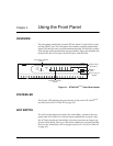
OVERVIEW
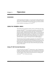
The front panel contains the System LED, the Alarm Cut-off (ACO) switch,
and the CRAFT port. The front panel also contains controller and module
status LEDs that provide visual information about the ATLAS 810
PLUS
Base
Unit and any option module that may be installed. Figure 4-1 identifies the
System LED, the ACO switch, the CRAFT port, and the LEDs.
Figure 4-1. ATLAS 810
PLUS
Front Panel Layout
SYSTEM LED
The System LED indicates the general status of the entire ATLAS 810
PLUS
(see also System LED in Table 4-2 on page 4-3).
ACO SWITCH
The ACO switch deactivates (clears) the Alarm Relay, located on the rear
panel of the ATLAS 810
PLUS
, after an alarm condition has occurred. After
the ACO has cleared the Alarm Relay, the same occurrence no longer trig-
gers the Alarm Relay. However, if the alarm condition is corrected and then
reoccurs, the Alarm Relay will re-energize (see also ACO Switch in Table 4-2
on page 4-3).
ATLAS 810
PLUS
CONTROLLER
OK
TEST
ERROR
ALARM
STATUS
ONLINE
TEST
1
2
3
4
5
67
8
MODULES
SYSTEM
ACO CRAFT
CRAFT
Port
Alarm Cut-off
Switch
Module Slot
Numbers
Module Status
LEDs
Controller Status
LEDs